Chapter 3---Electrical
Model 250 Service Manual
3-11
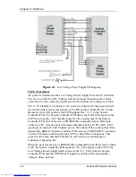
RGB Anode Voltage - goes directly to each CRT
RGB Focus Voltage - goes directly to each CRT
Arc Ground - The Arc Ground protection for each CRT from the Video Amplifier
PCB.
HVPS - Operation
The High Voltage Power Supply has three basic functions.
!
High Voltage Generation
!
Focus Voltages
!
High Voltage and CRT Protection
High Voltage Generation - The High Voltage Amplifier section converts the +80
V from the Low Voltage Power Supply, to 25 kV, and divides it into three outputs
for each CRT. It also uses the HVPS_SYNC signal from the Raster Timing
Generator PCB. This signal is synchronized to the horizontal sync to eliminate
one source of moving noise on the screen. The High Voltage section also supplies
the G
2
Voltage for the Video Amplifier PCB.
Focus Voltages - The High Voltage Power Supply receives the horizontal and
vertical parabolas from the Convergence Deflection PCB and adds them together.
They are amplified and sent to the Focus Pack section. The Focus Pack section
couples the amplified parabola waveforms to the Focus Voltages. The Focus Pack
divides the Focus Voltage into three signals and outputs each signal to a CRT.
The DC Focus Voltages are manually adjusted as necessary.
The Arc Ground signal goes to the Video Amplifier PCB and from there, connects
to the CRT. It provides a direct return path for arc currents in the event of internal
CRT arcing.
High Voltage and CRT Protection - The High Voltage Power Supply receives a
/HV_ENA (/VA_OK) signal from the Video Amplifier PCB. This signal goes to
the Protect OR section. The Protect OR section also checks the in80 V.
from the LVPS for an overcurrent condition. The Protect OR section also
monitors the high voltage output for an overvoltage condition. If any of these
checks shows a problem the Protect OR section shuts down the high voltage
amplifier. The Protect OR section outputs the /HV_OK signal telling the System
Controller PCB that the High Voltage Power Supply is functioning properly.
HVPS - Service Adjustments
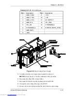
Normally, the only High Voltage Power Supply adjustments are for CRT Focus.
The CRT Focus Voltage adjusts are mechanical potentiometers located on the
side of the High Voltage Power Supply (see Figure 3-5) that adjust the focus for
each CRT. The CRT Focus Voltage adjustments are detailed in the CRT Section
(see section 5.10 CRT/Yoke Assemblies).
Содержание 250
Страница 16: ...Chapter 2 System Description Model 250 Service Manual 2 9 ...
Страница 43: ...Chapter 4 Optical 4 10 Model 250 Service Manual Figure 4 6 Optical Path ...
Страница 55: ...Chapter 5 Optical 3 4 22 Model 100 Service Manual ...
Страница 85: ...Chapter 5 Electronics 5 30 Model 250 Service Manual Figure 5 19 Convergence Deflection PCB I O Diagram ...
Страница 86: ...Chapter 5 Electronics Model 250 Service Manual 5 31 Figure 5 20 Convergence Deflection PCB I O Diagram ...
Страница 91: ...Chapter 5 Electronics 5 36 Model 250 Service Manual Figure 5 22 Scan Reversal PCB I O Diagram ...
Страница 100: ...Chapter 5 Electronics Model 250 Service Manual 5 45 Figure 5 26 Video Amplifier PCB I O Diagram ...
Страница 131: ...Chapter 5 Electronics 5 76 Model 250 Service Manual Figure 5 44 Backplane Diagram right side ...
Страница 132: ...Chapter 5 Electronics Model 250 Service Manual 5 77 ...
Страница 138: ...Chapter 6 Miscellaneous Items 6 6 Model 250 Service Manual ...
Страница 166: ...Chapter 7 Troubleshooting 7 28 Model 250 Service Manual Figure 7 19 Backplane Diagram right side ...
Страница 167: ...Chapter 7 Troubleshooting Model 250 Service Manual 7 29 ...
Страница 181: ...Chapter 8 Software and Protocol 8 14 Model 250 Service Manual ...
Страница 185: ...Chapter 9 Parts List 9 4 Model 250 Service Manual ...

