Chapter 5---Electronics
5-68
Model 250 Service Manual
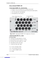
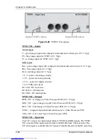
Figure 5-38
YPbPr VIC faceplate.
YPbPr VIC - Inputs
YPbPr Inputs
Y - green image input with composite horizontal and vertical sync (0.7-1 Vpp)
Pb - blue image input for YPbPr (0.7-1 Vpp)
Pr - red image input for YPbPr (0.7-1 Vpp)
GBR Inputs
Grn - green image input with composite horizontal and vertical sync (0.7-1 Vpp)
Blu - blue image input (0.7-1 Vpp)
Red - red image input (0.7-1 Vpp)
+15 V - power for analog circuitry
-15 V - power for analog circuitry
+5.1 V - power for digital circuitry
+5.1 V Stdby (not used)
IIC CLK - IIC clock line
IIC DATA - IIC data line
IIC SINT - IIC interrupt line
YPbPr VIC - Outputs
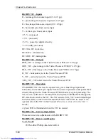
RED_VIC - red image to Video Processor PCB (0.7-1.0 Vpp).
GRN_VIC - green image to signal Video Processor PCB (0.7-1.0 Vpp).
BLU_VIC - blue image to Video Processor PCB (0.7-1.0 Vpp).
SYNC - composite horizontal and vertical sync to Video Processor PCB.
/SEL_VIC - VIC select line to Video Processor PCB.
YPbPr VIC - Operation
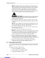
This VIC accepts two input signal formats, YPbPr and GBR signals. The YPbPr
VIC converts either input signal format to the RGB format. The selection of the
VIC and inputs is controlled by the System Controller Board via the IIC serial bus
Содержание 250
Страница 16: ...Chapter 2 System Description Model 250 Service Manual 2 9 ...
Страница 43: ...Chapter 4 Optical 4 10 Model 250 Service Manual Figure 4 6 Optical Path ...
Страница 55: ...Chapter 5 Optical 3 4 22 Model 100 Service Manual ...
Страница 85: ...Chapter 5 Electronics 5 30 Model 250 Service Manual Figure 5 19 Convergence Deflection PCB I O Diagram ...
Страница 86: ...Chapter 5 Electronics Model 250 Service Manual 5 31 Figure 5 20 Convergence Deflection PCB I O Diagram ...
Страница 91: ...Chapter 5 Electronics 5 36 Model 250 Service Manual Figure 5 22 Scan Reversal PCB I O Diagram ...
Страница 100: ...Chapter 5 Electronics Model 250 Service Manual 5 45 Figure 5 26 Video Amplifier PCB I O Diagram ...
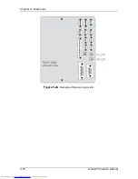
Страница 131: ...Chapter 5 Electronics 5 76 Model 250 Service Manual Figure 5 44 Backplane Diagram right side ...
Страница 132: ...Chapter 5 Electronics Model 250 Service Manual 5 77 ...
Страница 138: ...Chapter 6 Miscellaneous Items 6 6 Model 250 Service Manual ...
Страница 166: ...Chapter 7 Troubleshooting 7 28 Model 250 Service Manual Figure 7 19 Backplane Diagram right side ...
Страница 167: ...Chapter 7 Troubleshooting Model 250 Service Manual 7 29 ...
Страница 181: ...Chapter 8 Software and Protocol 8 14 Model 250 Service Manual ...
Страница 185: ...Chapter 9 Parts List 9 4 Model 250 Service Manual ...

