Chapter 2---System Description
2-4
Model 250 Service Manual
!
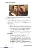
Condensing Lenses (2) - The Primary Condensing Lens collects all the
light from the Light Pipe and begins to bend the light rays into a straight
path. The Secondary Condensing Lens works with the Primary
Condensing Lens to collimate or “straighten” the light path before it enters
the Dichroic Beamsplitter Assembly.
!
UV Filter - The UV Filter removes much of the unwanted ultravioltet light
from the white light of the Arc Lamp.
!
Dichroic Beamsplitter Assembly w/ Steering Mirrors - The Dichroic
Mirrors separate white light into Red, Green, and Blue component colors.
The Steering Mirrors direct the separated light beams into the Prism
Assembly.
!
Prism Assembly - The Prism Assembly is a large tank filled with optical
fluid. It houses the following optical components:
"
Pre-polarizing Beamsplitter - The Pre-polarizing Beamsplitter
performs the first part of the polarizing process.
"
Polarizing Beamsplitter - The Polarizing Beamsplitter performs the
final function of the polarizing process.
"
Steering Prisms - When the polarized light leaves the Prism
Assembly and enters the ILA
®
, the light is modulated by the ILA
®
.
The modulated light reflects off the ILA
®
mirror and returns to the
Prism Assembly. Inside the Prism Assembly, the light for the red and
blue reflect off the two Steering Mirrors (one for red, one for blue)
and enter the 4P Combining Optic.
"
4P Combining Optic - The 4P Combining Optic takes the three
colored image lights from the ILA
®
s and combines them so they
leave the Prism Assembly as a single beam of image light. That
image light continues on to the Projection Lens
ILA
®
s - Image Light Amplifier (3)
The ILA
®
is a very important component in the Hughes-JVC projectors. The
ILA
®
modulates the polarized light from the Arc Lamp. The image light from the
CRT that strikes the input side of the ILA
®
interacts with the Liquid Crystal layer
of the ILA
®
to impose an image on the polarized light from the Arc Lamp. The
Model 250 Projector uses the Super Contrast ILA
®
. The Super Contrast ILA
®
has
a sequential contrast ratio of 600:1 @ center screen.
CRTs (3)
There are three Cathode Ray Tubes (CRTs), one for each color. The CRT
generates the image light that strikes the input of the ILA
®
. CRTs are covered in
the Electronics Section.
Содержание 250
Страница 16: ...Chapter 2 System Description Model 250 Service Manual 2 9 ...
Страница 43: ...Chapter 4 Optical 4 10 Model 250 Service Manual Figure 4 6 Optical Path ...
Страница 55: ...Chapter 5 Optical 3 4 22 Model 100 Service Manual ...
Страница 85: ...Chapter 5 Electronics 5 30 Model 250 Service Manual Figure 5 19 Convergence Deflection PCB I O Diagram ...
Страница 86: ...Chapter 5 Electronics Model 250 Service Manual 5 31 Figure 5 20 Convergence Deflection PCB I O Diagram ...
Страница 91: ...Chapter 5 Electronics 5 36 Model 250 Service Manual Figure 5 22 Scan Reversal PCB I O Diagram ...
Страница 100: ...Chapter 5 Electronics Model 250 Service Manual 5 45 Figure 5 26 Video Amplifier PCB I O Diagram ...
Страница 131: ...Chapter 5 Electronics 5 76 Model 250 Service Manual Figure 5 44 Backplane Diagram right side ...
Страница 132: ...Chapter 5 Electronics Model 250 Service Manual 5 77 ...
Страница 138: ...Chapter 6 Miscellaneous Items 6 6 Model 250 Service Manual ...
Страница 166: ...Chapter 7 Troubleshooting 7 28 Model 250 Service Manual Figure 7 19 Backplane Diagram right side ...
Страница 167: ...Chapter 7 Troubleshooting Model 250 Service Manual 7 29 ...
Страница 181: ...Chapter 8 Software and Protocol 8 14 Model 250 Service Manual ...
Страница 185: ...Chapter 9 Parts List 9 4 Model 250 Service Manual ...


