Chapter 3---Electrical
Model 250 Service Manual
3-7
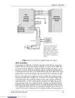
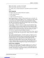
Figure 3-2
Arc Lamp Power Supply signals and voltages.
ALPS - Operation:
Three signals (/LAMP_ENA, /COVER_ON, and /LAMP_OK) are required in
order for the Arc Lamp Power Supply to light the Arc Lamp. The /LAMP_OK
(active low) input is jumpered to ground at the Arc Lamp Power Supply, so it is
always low. The Arc Lamp Power Supply sends the /LAMP_OK to the System
Controller PCB. The System Controller PCB then sends the /LAMP_ENA signal
back to the Arc Lamp Power Supply and activates the Arc Lamp Power Supply.
Once the Arc Lamp Power Supply receives the /LAMP_ENA signal from the
System Controller PCB, it supplies the +170 VDC boost voltage to the primary
coil of the Igniter. The Laser Power Supply charges up a capacitor. When the
capacitor reaches +5.5 kV, a spark gap arcs causing a very high voltage pulse
(approximately 32 kV) to be induced onto the secondary coil inside the Igniter.
This high voltage pulse ignites the Xenon Arc Lamp. Immediately after the Arc
Lamp lights, the voltage from the Arc Lamp Power Supply drops to about 25-31
volts at 70-85 amps. It will stay at this level during normal Arc Lamp operation.
Содержание 250
Страница 16: ...Chapter 2 System Description Model 250 Service Manual 2 9 ...
Страница 43: ...Chapter 4 Optical 4 10 Model 250 Service Manual Figure 4 6 Optical Path ...
Страница 55: ...Chapter 5 Optical 3 4 22 Model 100 Service Manual ...
Страница 85: ...Chapter 5 Electronics 5 30 Model 250 Service Manual Figure 5 19 Convergence Deflection PCB I O Diagram ...
Страница 86: ...Chapter 5 Electronics Model 250 Service Manual 5 31 Figure 5 20 Convergence Deflection PCB I O Diagram ...
Страница 91: ...Chapter 5 Electronics 5 36 Model 250 Service Manual Figure 5 22 Scan Reversal PCB I O Diagram ...
Страница 100: ...Chapter 5 Electronics Model 250 Service Manual 5 45 Figure 5 26 Video Amplifier PCB I O Diagram ...
Страница 131: ...Chapter 5 Electronics 5 76 Model 250 Service Manual Figure 5 44 Backplane Diagram right side ...
Страница 132: ...Chapter 5 Electronics Model 250 Service Manual 5 77 ...
Страница 138: ...Chapter 6 Miscellaneous Items 6 6 Model 250 Service Manual ...
Страница 166: ...Chapter 7 Troubleshooting 7 28 Model 250 Service Manual Figure 7 19 Backplane Diagram right side ...
Страница 167: ...Chapter 7 Troubleshooting Model 250 Service Manual 7 29 ...
Страница 181: ...Chapter 8 Software and Protocol 8 14 Model 250 Service Manual ...
Страница 185: ...Chapter 9 Parts List 9 4 Model 250 Service Manual ...

