Chapter 5---Electronics
Model 250 Service Manual
5-53
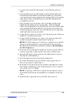
CRT Mechanical Focus
The CRT Mechanical focus is factory-set and normally will not require additional
adjustment unless a CRT has been replaced. After replacing a CRT, reset the
mechanical focus. After completing the CRT installation and mechanical focus,
check the other CRTs for convergence and shading.
Tools Needed
1.5-mm Hex-head wrench
#0 Pozi-drive Phillips-head screwdriver
To adjust the CRT Mechanical Focus:
1.
Remove the rear cover.
2.
Pull the Interlock Switch for the rear cover up to the Service Mode
position.
3.
Power the projector ON and allow it to stabilize for at least 15 minutes.
4.
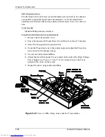
Tilt the Electronic Module to the full up position.
5.
Select the Focus pattern (test pattern #6).
6.
Zoom the Projection Lens to the widest angle (largest image) and adjust
the Projection Lens focus for the sharpest image of the Focus test pattern.
7.
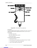
Loosen the two setscrews (see Figure 5-29) near the top of the CRT sleeve
using the 1.5-mm Hex-head wrench.
8.
Loosen the CRT focus lock screw located on the Guide Plate at the top of
the CRT shield (see Figure 5-29). The CRT is now free to slide.
9.
Grasp the CRT thumbscrew (see Figure 5-29) and slide the CRT forward
and backward until the image is focused as sharply as possible (be careful
not to loosen the CRT thumbscrew, which could allow the CRT to rotate).
10.
Tighten the setscrews first, then the CRT focus lock screw.
NOTE:
Tighten the setscrews before tightening the focus lock screw. If
the setscrews are loose the focus lock screw can slightly defocus or rotate
the CRT as it is being tightened.
11.
Repeat the above steps for the Red and Blue CRTs.
Содержание 250
Страница 16: ...Chapter 2 System Description Model 250 Service Manual 2 9 ...
Страница 43: ...Chapter 4 Optical 4 10 Model 250 Service Manual Figure 4 6 Optical Path ...
Страница 55: ...Chapter 5 Optical 3 4 22 Model 100 Service Manual ...
Страница 85: ...Chapter 5 Electronics 5 30 Model 250 Service Manual Figure 5 19 Convergence Deflection PCB I O Diagram ...
Страница 86: ...Chapter 5 Electronics Model 250 Service Manual 5 31 Figure 5 20 Convergence Deflection PCB I O Diagram ...
Страница 91: ...Chapter 5 Electronics 5 36 Model 250 Service Manual Figure 5 22 Scan Reversal PCB I O Diagram ...
Страница 100: ...Chapter 5 Electronics Model 250 Service Manual 5 45 Figure 5 26 Video Amplifier PCB I O Diagram ...
Страница 131: ...Chapter 5 Electronics 5 76 Model 250 Service Manual Figure 5 44 Backplane Diagram right side ...
Страница 132: ...Chapter 5 Electronics Model 250 Service Manual 5 77 ...
Страница 138: ...Chapter 6 Miscellaneous Items 6 6 Model 250 Service Manual ...
Страница 166: ...Chapter 7 Troubleshooting 7 28 Model 250 Service Manual Figure 7 19 Backplane Diagram right side ...
Страница 167: ...Chapter 7 Troubleshooting Model 250 Service Manual 7 29 ...
Страница 181: ...Chapter 8 Software and Protocol 8 14 Model 250 Service Manual ...
Страница 185: ...Chapter 9 Parts List 9 4 Model 250 Service Manual ...


