Chapter 3---Electrical
Model 250 Service Manual
3-17
5.
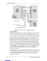
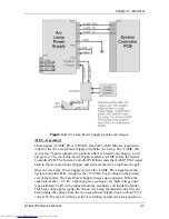
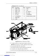
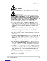
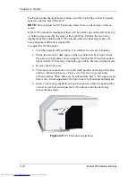
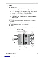
Disconnect the orange cable attached to the input side of the Igniter
Transformer using the 7/16-inch wrench. This cable will have black shrink
sleeving on it. It goes to the negative terminal of the Arc Lamp Power
Supply.
6.
Disconnect the orange Cathode cable from the Igniter ground post using
the 7/16-inch wrench. Remove the other orange cable that goes to the
positive terminal of the Arc Lamp Power Supply.
7.
Remove the five #1 Pozi-drive Phillips-head screws.
8.
Lift the Igniter Assembly out of projector.
9.
Reverse the procedure to install the Igniter Assembly.
Содержание 250
Страница 16: ...Chapter 2 System Description Model 250 Service Manual 2 9 ...
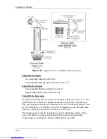
Страница 43: ...Chapter 4 Optical 4 10 Model 250 Service Manual Figure 4 6 Optical Path ...
Страница 55: ...Chapter 5 Optical 3 4 22 Model 100 Service Manual ...
Страница 85: ...Chapter 5 Electronics 5 30 Model 250 Service Manual Figure 5 19 Convergence Deflection PCB I O Diagram ...
Страница 86: ...Chapter 5 Electronics Model 250 Service Manual 5 31 Figure 5 20 Convergence Deflection PCB I O Diagram ...
Страница 91: ...Chapter 5 Electronics 5 36 Model 250 Service Manual Figure 5 22 Scan Reversal PCB I O Diagram ...
Страница 100: ...Chapter 5 Electronics Model 250 Service Manual 5 45 Figure 5 26 Video Amplifier PCB I O Diagram ...
Страница 131: ...Chapter 5 Electronics 5 76 Model 250 Service Manual Figure 5 44 Backplane Diagram right side ...
Страница 132: ...Chapter 5 Electronics Model 250 Service Manual 5 77 ...
Страница 138: ...Chapter 6 Miscellaneous Items 6 6 Model 250 Service Manual ...
Страница 166: ...Chapter 7 Troubleshooting 7 28 Model 250 Service Manual Figure 7 19 Backplane Diagram right side ...
Страница 167: ...Chapter 7 Troubleshooting Model 250 Service Manual 7 29 ...
Страница 181: ...Chapter 8 Software and Protocol 8 14 Model 250 Service Manual ...
Страница 185: ...Chapter 9 Parts List 9 4 Model 250 Service Manual ...


