Chapter 4---Optical
4-20
Model 250 Service Manual
4.4 Relay
Lenses
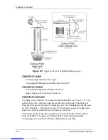
The Relay Lens focuses the image light received from the CRT on the
photoconductive layer of the ILA
®
(see Figure 4-9). There are no service
adjustments for the Relay Lens. The Relay Lens rarely needs service and is not
considered a serviceable part.
4.5 Projection
Lens
Projection Lens - Input
Combined RGB image light from the Prism Assembly.
Projection Lens - Output
Output image light to the screen
Projection Lens - Operation
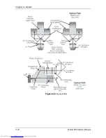
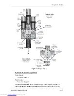
The projection lens receives image light from the Prism Assembly. The light is
high intensity light from the ILA
®
that has been modulated by the image light
from the CRT. After leaving the ILA
®
s the modulated light travels back through
the Prism Assembly where the red, green, and blue image light are combined. The
Projection Lens focuses this output image light onto the screen. All Projection
Lenses come with motorized focus adjustment.
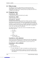
The Model 250 projector comes with a choice of four standard lens options.
Motorized Zoom Lens
2:1 - 4:1
!
Fixed Lenses
0.96: 1
1.5: 1
5.6:1
!
Optional Lenses
2.4:1 Simulator Lens
Projection Lens - Service Adjustments
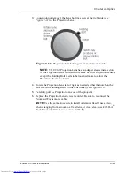
There are no service adjustments for the Projection Lens. The focus adjustment,
both rough and fine focus adjustments, are part of the projector setup procedure
(see Model 250 User’s Guide, Setup Adjustments sections 5.4 and 5.5.15)
Projection Lens - Remove and Replace
Tools Needed
5-mm Hex wrench
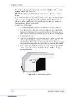
To remove the Projection Lens:
1.
Remove the sponge cover that is around the front of the Projection Lens.
2.
Disconnect and label the Projection Lens Focus and Zoom motor cables
(The Focus motor is at the top of the Projection Lens. The Zoom motor is
at the bottom.)
Содержание 250
Страница 16: ...Chapter 2 System Description Model 250 Service Manual 2 9 ...
Страница 43: ...Chapter 4 Optical 4 10 Model 250 Service Manual Figure 4 6 Optical Path ...
Страница 55: ...Chapter 5 Optical 3 4 22 Model 100 Service Manual ...
Страница 85: ...Chapter 5 Electronics 5 30 Model 250 Service Manual Figure 5 19 Convergence Deflection PCB I O Diagram ...
Страница 86: ...Chapter 5 Electronics Model 250 Service Manual 5 31 Figure 5 20 Convergence Deflection PCB I O Diagram ...
Страница 91: ...Chapter 5 Electronics 5 36 Model 250 Service Manual Figure 5 22 Scan Reversal PCB I O Diagram ...
Страница 100: ...Chapter 5 Electronics Model 250 Service Manual 5 45 Figure 5 26 Video Amplifier PCB I O Diagram ...
Страница 131: ...Chapter 5 Electronics 5 76 Model 250 Service Manual Figure 5 44 Backplane Diagram right side ...
Страница 132: ...Chapter 5 Electronics Model 250 Service Manual 5 77 ...
Страница 138: ...Chapter 6 Miscellaneous Items 6 6 Model 250 Service Manual ...
Страница 166: ...Chapter 7 Troubleshooting 7 28 Model 250 Service Manual Figure 7 19 Backplane Diagram right side ...
Страница 167: ...Chapter 7 Troubleshooting Model 250 Service Manual 7 29 ...
Страница 181: ...Chapter 8 Software and Protocol 8 14 Model 250 Service Manual ...
Страница 185: ...Chapter 9 Parts List 9 4 Model 250 Service Manual ...


