Chapter 3---Electrical
Model 250 Service Manual
3-3
3.3 Power
Supplies
All Series 200 projectors including the Model 250 have three power supplies.
These include:
!
Low Voltage Power Supply
!
Arc Lamp Power Supply
!
High Voltage Power Supply
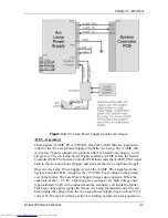
There is a fourth power supply, the Laser Power Supply, but that power supply is
used only for the Igniter Assembly during Arc Lamp lighting.
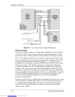
Low Voltage Power Supply (LVPS)
LVPS - Main Functions:
!
Provides all the low voltages needed by the projector.
!
Provides standby power (+5.1V) when the projector is OFF but the AC
Circuit Breaker is in the ON position.
!
Provides power (+24 V) for all cooling fans.
LVPS - Inputs
:
The Low Voltage Power Supply receives AC input power directly from the AC
Line Filter. The input range is from 220 VAC to 240 VAC, at 50/60 Hz.
/LV_ENA - from the System Controller PCB. This signal enables the LVPS when
the System Controller receives a Power On command.
/FAN_ENA - from the System Controller PCB. This signal enables the +24v
standby voltage for the projector fans.
/COVER_ON - signal enables the non-standby outputs.
/ = Active low
LVPS - Outputs:
!
+ 5.1VDC Main
!
+ 5.1VDC Stdby
!
+ 6.2VDC
!
± 15VDC
!
+ 24VDC
!
+ 80VDC
/LV_OK - this diagnostic signal tells the System Controller PCB the status of the
non-standby supply (all the outputs are working or not working).
Содержание 250
Страница 16: ...Chapter 2 System Description Model 250 Service Manual 2 9 ...
Страница 43: ...Chapter 4 Optical 4 10 Model 250 Service Manual Figure 4 6 Optical Path ...
Страница 55: ...Chapter 5 Optical 3 4 22 Model 100 Service Manual ...
Страница 85: ...Chapter 5 Electronics 5 30 Model 250 Service Manual Figure 5 19 Convergence Deflection PCB I O Diagram ...
Страница 86: ...Chapter 5 Electronics Model 250 Service Manual 5 31 Figure 5 20 Convergence Deflection PCB I O Diagram ...
Страница 91: ...Chapter 5 Electronics 5 36 Model 250 Service Manual Figure 5 22 Scan Reversal PCB I O Diagram ...
Страница 100: ...Chapter 5 Electronics Model 250 Service Manual 5 45 Figure 5 26 Video Amplifier PCB I O Diagram ...
Страница 131: ...Chapter 5 Electronics 5 76 Model 250 Service Manual Figure 5 44 Backplane Diagram right side ...
Страница 132: ...Chapter 5 Electronics Model 250 Service Manual 5 77 ...
Страница 138: ...Chapter 6 Miscellaneous Items 6 6 Model 250 Service Manual ...
Страница 166: ...Chapter 7 Troubleshooting 7 28 Model 250 Service Manual Figure 7 19 Backplane Diagram right side ...
Страница 167: ...Chapter 7 Troubleshooting Model 250 Service Manual 7 29 ...
Страница 181: ...Chapter 8 Software and Protocol 8 14 Model 250 Service Manual ...
Страница 185: ...Chapter 9 Parts List 9 4 Model 250 Service Manual ...

