Chapter 5---Electronics
Model 250 Service Manual
5-61
Parts Needed
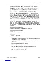
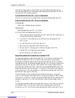
RGBHV VIC p/n 102597
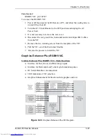
To remove the RGBHV VIC:
1.
Power off the projector by IR Remote or PC, and allow the cooling fans to
run until they shut off.
2.
Turn the AC Circuit Breaker to the OFF position and unplug the AC
Power Cord.
3.
It is not necessary to remove the rear cover.
4.
Disconnect the red, green blue, horizontal and vertical input BNC cables
from the VIC.
5.
Remove the two retaining screws from the faceplate of the VIC.
6.
Pull the VIC out of the Electronics Module.
7.
Reverse the process to install the VIC.
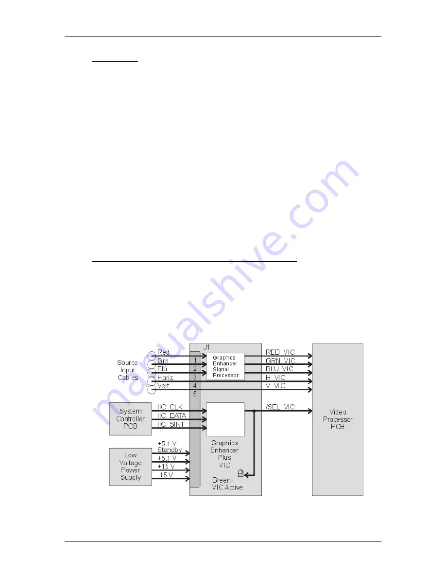
Graphics Enhancer Plus RGBHV VIC
Grahics Enhancer Plus RGBHV VIC - Main Functions
!
Interface for Red, Green, and Blue image inputs
!
Interface for Horizontal and Vertical synchronization pulses
!
IIC Serial Data Bus communication
!
LED indication of VIC selection
!
Graphics Enhancement for black-on-white graphics and text.
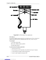
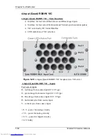
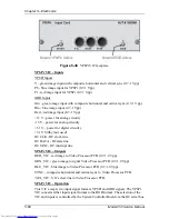
Figure 5-33
Graphics Enhancer Plus I/O Diagram.
Содержание 250
Страница 16: ...Chapter 2 System Description Model 250 Service Manual 2 9 ...
Страница 43: ...Chapter 4 Optical 4 10 Model 250 Service Manual Figure 4 6 Optical Path ...
Страница 55: ...Chapter 5 Optical 3 4 22 Model 100 Service Manual ...
Страница 85: ...Chapter 5 Electronics 5 30 Model 250 Service Manual Figure 5 19 Convergence Deflection PCB I O Diagram ...
Страница 86: ...Chapter 5 Electronics Model 250 Service Manual 5 31 Figure 5 20 Convergence Deflection PCB I O Diagram ...
Страница 91: ...Chapter 5 Electronics 5 36 Model 250 Service Manual Figure 5 22 Scan Reversal PCB I O Diagram ...
Страница 100: ...Chapter 5 Electronics Model 250 Service Manual 5 45 Figure 5 26 Video Amplifier PCB I O Diagram ...
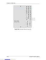
Страница 131: ...Chapter 5 Electronics 5 76 Model 250 Service Manual Figure 5 44 Backplane Diagram right side ...
Страница 132: ...Chapter 5 Electronics Model 250 Service Manual 5 77 ...
Страница 138: ...Chapter 6 Miscellaneous Items 6 6 Model 250 Service Manual ...
Страница 166: ...Chapter 7 Troubleshooting 7 28 Model 250 Service Manual Figure 7 19 Backplane Diagram right side ...
Страница 167: ...Chapter 7 Troubleshooting Model 250 Service Manual 7 29 ...
Страница 181: ...Chapter 8 Software and Protocol 8 14 Model 250 Service Manual ...
Страница 185: ...Chapter 9 Parts List 9 4 Model 250 Service Manual ...

