Chapter 5---Electronics
Model 250 Service Manual
5-19
V_DRIVE - square wave negative going pulse to the Convergence Deflection
PCB, synchronized to the selected vertical sync with the pulse width of about four
horizontal periods.
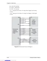
Raster Timing Generator PCB - Operation
The Raster Timing Generator PCB generates a square wave that is phase-locked
to the horizontal sync pulse. It generates timing signals such as Blanking that goes
to the Video Processor PCB and Video Amplifier PCB, and the H_DRIVE signal
that goes to the Horizontal Vertical Deflection PCB. The PLL (Phase Locked
Loop) locks these signals to the horizontal sync signal. The Raster Timing
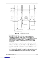
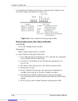
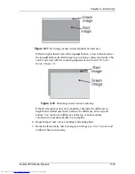
Generator PCB has LEDs that indicate the type of sync pulse received and the
status of the PLL circuit (see Figure 5-12).
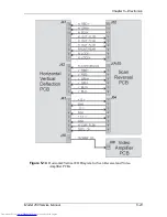
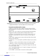
The H_DRIVE signal supplies a sample of the horizontal scan frequency to the
horizontal deflection amplifier on the Horizontal Vertical Deflection PCB for
timing of the horizontal deflection waveform.
The Raster Timing Generator PCB checks the incoming syncs to make sure they
are valid signals and within the frequency ranges (15 - 90 kHz - horizontal, and 45
- 120 Hz vertical). If the syncs are out of range, or there is no sync pulse, the
Raster Timing Generator PCB generates an internal interlaced sync at 33.7 kHz
horizontal and 60 Hz vertical.
The Raster Timing Generator PCB tells the System Controller PCB when there
has been a source change using the SOURCE_VALID signal.
The Raster Timing Generator PCB generates the Blanking signal, and the
horizontal Phase signal.
!
Blanking shuts off the image during times where there is no active video. The
Blanking signal pulls the G1 voltage on the Video Amplifier PCB down far
enough to make the CRT shut off. The Raster Timing Generator PCB receives
the top, bottom, left, or right blanking command on the IIC bus and sends the
appropriate Blanking signal to the Video Processor PCB. The Raster Timing
Generator PCB receives the Blanking adjustment commands on the IIC bus.
!
The horizontal Phase signal adjusts the on-screen image horizontally to
compensate for different phase requirements at different horizontal scan
frequencies. The Raster Timing Generator PCB receives this command from
the System Controller PCB on the IIC bus.
The Raster Timing Generator PCB sends several signals such as 280_CLOCK
signal to the System Controller PCB to correctly set the timing for shading and
convergence data.
In order to combat noise caused by crosstalk between supplies (beat patterns) the
High Voltage Power Supply is phase locked to the incoming horizontal frequency
by the HVPS_SYNC signal.
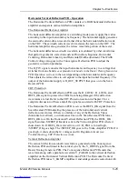
The horizontal flyback time gets shorter as the horizontal scan frequency
increases. The Raster Timing Generator PCB works together with the Horizontal
Содержание 250
Страница 16: ...Chapter 2 System Description Model 250 Service Manual 2 9 ...
Страница 43: ...Chapter 4 Optical 4 10 Model 250 Service Manual Figure 4 6 Optical Path ...
Страница 55: ...Chapter 5 Optical 3 4 22 Model 100 Service Manual ...
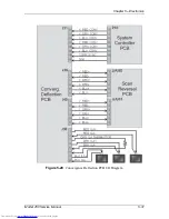
Страница 85: ...Chapter 5 Electronics 5 30 Model 250 Service Manual Figure 5 19 Convergence Deflection PCB I O Diagram ...
Страница 86: ...Chapter 5 Electronics Model 250 Service Manual 5 31 Figure 5 20 Convergence Deflection PCB I O Diagram ...
Страница 91: ...Chapter 5 Electronics 5 36 Model 250 Service Manual Figure 5 22 Scan Reversal PCB I O Diagram ...
Страница 100: ...Chapter 5 Electronics Model 250 Service Manual 5 45 Figure 5 26 Video Amplifier PCB I O Diagram ...
Страница 131: ...Chapter 5 Electronics 5 76 Model 250 Service Manual Figure 5 44 Backplane Diagram right side ...
Страница 132: ...Chapter 5 Electronics Model 250 Service Manual 5 77 ...
Страница 138: ...Chapter 6 Miscellaneous Items 6 6 Model 250 Service Manual ...
Страница 166: ...Chapter 7 Troubleshooting 7 28 Model 250 Service Manual Figure 7 19 Backplane Diagram right side ...
Страница 167: ...Chapter 7 Troubleshooting Model 250 Service Manual 7 29 ...
Страница 181: ...Chapter 8 Software and Protocol 8 14 Model 250 Service Manual ...
Страница 185: ...Chapter 9 Parts List 9 4 Model 250 Service Manual ...

