Chapter 5---Electronics
Model 250 Service Manual
5-21
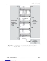
5.6 Horizontal Vertical Deflection PCB
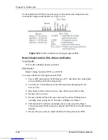
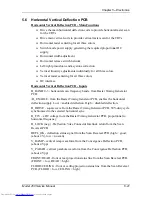
Horizontal Vertical Deflection PCB - Main Functions
!
Drive the main horizontal deflection coils to provide horizontal raster scan
for the CRTs
!
Drive main vertical coils to provide vertical raster scan for the CRTs
!
Horizontal raster centering for all three colors
!
Switch mode power supply generating the required proportional DC
supply
!
Horizontal width adjustment
!
Horizontal retrace switch network
!
Left/right pincushion and keystone correction
!
Vertical linearity adjustments individually for all three colors.
!
Vertical raster centering for all three colors
!
IIC interface.
Horizontal Vertical Deflection PCB - Inputs
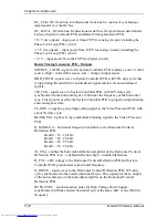
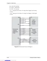
H_BAND:0-3 - horizontal scan frequency bands, from Raster Timing Generator
PCB.
/H_ENABLE - from the Raster Timing Generator PCB, enables the horizontal
deflection supply. Low = enabled deflection, High = disabled deflection.
H_DRIVE - square wave from the Raster Timing Generator PCB, 50% duty cycle
synchronized to the selected horizontal sync.
H_F2V - a DC voltage from the Raster Timing Generator PCB, proportional to
horizontal frequency
H_LOCK (neg.) - Deflection Yoke Connector Interlock return from the Scan
Reversal PCB.
DEFL_OK - deflection status signal from the Scan Reversal PCB (high = good,
(about 2 V), low = no scan).
V_RAMP - vertical ramp waveform from the Convergence Deflection PCB,
(about 4 Vpp).
V_PARAB - vertical parabola waveform from the Convergence Deflection PCB,
(about 4 Vpp).
FRONT/REAR - front or rear projection status line from the Scan Reversal PCB.
(FRONT = low, REAR = high).
FLOOR/CEILING - floor or ceiling projection status line from the Scan Reversal
PCB. (FLOOR = low, CEILING = high).
Содержание 250
Страница 16: ...Chapter 2 System Description Model 250 Service Manual 2 9 ...
Страница 43: ...Chapter 4 Optical 4 10 Model 250 Service Manual Figure 4 6 Optical Path ...
Страница 55: ...Chapter 5 Optical 3 4 22 Model 100 Service Manual ...
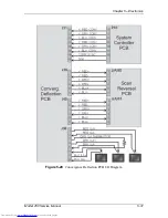
Страница 85: ...Chapter 5 Electronics 5 30 Model 250 Service Manual Figure 5 19 Convergence Deflection PCB I O Diagram ...
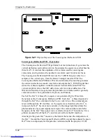
Страница 86: ...Chapter 5 Electronics Model 250 Service Manual 5 31 Figure 5 20 Convergence Deflection PCB I O Diagram ...
Страница 91: ...Chapter 5 Electronics 5 36 Model 250 Service Manual Figure 5 22 Scan Reversal PCB I O Diagram ...
Страница 100: ...Chapter 5 Electronics Model 250 Service Manual 5 45 Figure 5 26 Video Amplifier PCB I O Diagram ...
Страница 131: ...Chapter 5 Electronics 5 76 Model 250 Service Manual Figure 5 44 Backplane Diagram right side ...
Страница 132: ...Chapter 5 Electronics Model 250 Service Manual 5 77 ...
Страница 138: ...Chapter 6 Miscellaneous Items 6 6 Model 250 Service Manual ...
Страница 166: ...Chapter 7 Troubleshooting 7 28 Model 250 Service Manual Figure 7 19 Backplane Diagram right side ...
Страница 167: ...Chapter 7 Troubleshooting Model 250 Service Manual 7 29 ...
Страница 181: ...Chapter 8 Software and Protocol 8 14 Model 250 Service Manual ...
Страница 185: ...Chapter 9 Parts List 9 4 Model 250 Service Manual ...

