Chapter 5---Electronics
5-56
Model 250 Service Manual
CRT Electronic Focus
The Electronic Focus is factory-set and normally will not need to be adjusted
except after component replacement, maintenance, or if wide temperature
variations exist between the factory and the field location. View one color at a
time.
Tools Needed
Medium Phillips-head screwdriver
To perform the Electronic Focus adjustment:
1.
Remove the front and rear cover.
2.
Power the projector ON and allow it to stabilize for at least 15 minutes.
3.
Select the Focus pattern (test pattern #6).
4.
Zoom the Projection Lens to the widest angle and adjust the Projection
Lens focus for the sharpest image.
5.
View Green. Hide Red and Blue.
6.
Adjust the Green Electronic Focus located on the side of the High Voltage
Power Supply (see Figure 3-5 and 3-6) for a sharp focus of the Focus
pattern at the center of the screen.
7.
Repeat the above steps for Red and Blue.
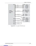
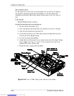
Figure 5-30
View of CRTs, Relay lenses and ILA
®
Assemblies
.
Содержание 250
Страница 16: ...Chapter 2 System Description Model 250 Service Manual 2 9 ...
Страница 43: ...Chapter 4 Optical 4 10 Model 250 Service Manual Figure 4 6 Optical Path ...
Страница 55: ...Chapter 5 Optical 3 4 22 Model 100 Service Manual ...
Страница 85: ...Chapter 5 Electronics 5 30 Model 250 Service Manual Figure 5 19 Convergence Deflection PCB I O Diagram ...
Страница 86: ...Chapter 5 Electronics Model 250 Service Manual 5 31 Figure 5 20 Convergence Deflection PCB I O Diagram ...
Страница 91: ...Chapter 5 Electronics 5 36 Model 250 Service Manual Figure 5 22 Scan Reversal PCB I O Diagram ...
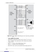
Страница 100: ...Chapter 5 Electronics Model 250 Service Manual 5 45 Figure 5 26 Video Amplifier PCB I O Diagram ...
Страница 131: ...Chapter 5 Electronics 5 76 Model 250 Service Manual Figure 5 44 Backplane Diagram right side ...
Страница 132: ...Chapter 5 Electronics Model 250 Service Manual 5 77 ...
Страница 138: ...Chapter 6 Miscellaneous Items 6 6 Model 250 Service Manual ...
Страница 166: ...Chapter 7 Troubleshooting 7 28 Model 250 Service Manual Figure 7 19 Backplane Diagram right side ...
Страница 167: ...Chapter 7 Troubleshooting Model 250 Service Manual 7 29 ...
Страница 181: ...Chapter 8 Software and Protocol 8 14 Model 250 Service Manual ...
Страница 185: ...Chapter 9 Parts List 9 4 Model 250 Service Manual ...


