Chapter 5---Electronics
Model 250 Service Manual
5-57
CRT/Yoke Assemblies - Remove and Replace
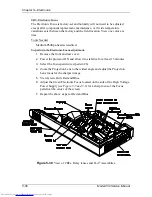
Three CRT/Yoke Assemblies are located in the CRT Assembly area below the
card cage (see Figure 5-30).
WARNING!!!
Handle the CRT/Yoke Assemblies with
extreme caution. If they are dropped, they can implode and flying glass
can cause severe injury to personnel. Be careful not to bump or drop the
CRT. Immediately after removal, place the CRT/Yoke in a safe area.
Procedure to remove a CRT/Yoke Assembly:
Tools Needed
#0 Pozi-drive Phillips-head screwdriver
Parts Needed
CRT p/n 105199
To remove and replace a CRT:
1.
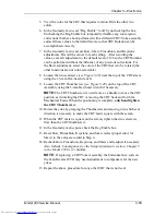
Power OFF the projector by IR Remote or PC, and allow the cooling fans
to run until they shut off automatically.
2.
Turn the AC Circuit Breaker to the OFF position and unplug the AC
Power Cord.
3.
Remove front and rear covers.
4.
Tilt the Electronic Module up and lock it in place.
5.
Loosen the two Pozi-drive Phillips-head screws from the top of the High
Voltage Power Supply cover. Remove the one Pozi-drive Phillips-head
screw at the bottom of the cover.
6.
Remove the CRT Anode cable of the CRT being replaced from the High
Voltage Power Supply.
7.
Disconnect the Yoke plug and cable harness from the Scan Reversal PCB
for the appropriate CRT (see Figure 5-25).
8.
Remove the wires from the cable clamp for the CRT/Yoke Assembly
being removed.
9.
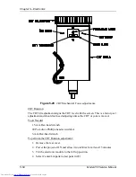
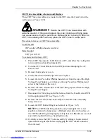
Loosen the CRT Holder Ring (knurled knob in Figure 5-29).
NOTE:
The CRT Holder Ring should be only hand-tight. If it is not
possible to remove by hand, place a Flathead screwdriver in the slots on
the CRT Holder Ring and tap lightly to help loosen it. Do not use a tool of
any kind to tighten this ring - hand tighten only.
10.
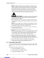
Carefully remove the CRT/Yoke Assembly by sliding it backward and
upward as far as possible before unplugging the CRT socket connector
from the neck.
Содержание 250
Страница 16: ...Chapter 2 System Description Model 250 Service Manual 2 9 ...
Страница 43: ...Chapter 4 Optical 4 10 Model 250 Service Manual Figure 4 6 Optical Path ...
Страница 55: ...Chapter 5 Optical 3 4 22 Model 100 Service Manual ...
Страница 85: ...Chapter 5 Electronics 5 30 Model 250 Service Manual Figure 5 19 Convergence Deflection PCB I O Diagram ...
Страница 86: ...Chapter 5 Electronics Model 250 Service Manual 5 31 Figure 5 20 Convergence Deflection PCB I O Diagram ...
Страница 91: ...Chapter 5 Electronics 5 36 Model 250 Service Manual Figure 5 22 Scan Reversal PCB I O Diagram ...
Страница 100: ...Chapter 5 Electronics Model 250 Service Manual 5 45 Figure 5 26 Video Amplifier PCB I O Diagram ...
Страница 131: ...Chapter 5 Electronics 5 76 Model 250 Service Manual Figure 5 44 Backplane Diagram right side ...
Страница 132: ...Chapter 5 Electronics Model 250 Service Manual 5 77 ...
Страница 138: ...Chapter 6 Miscellaneous Items 6 6 Model 250 Service Manual ...
Страница 166: ...Chapter 7 Troubleshooting 7 28 Model 250 Service Manual Figure 7 19 Backplane Diagram right side ...
Страница 167: ...Chapter 7 Troubleshooting Model 250 Service Manual 7 29 ...
Страница 181: ...Chapter 8 Software and Protocol 8 14 Model 250 Service Manual ...
Страница 185: ...Chapter 9 Parts List 9 4 Model 250 Service Manual ...


