Chapter 3---Electrical
Model 250 Service Manual
3-15
3.4 Igniter
Assembly
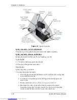
The Igniter Assembly consists of the Igniter and the Laser Power Supply. The
Igniter and Laser Power Supply are replaced as one unit.
Igniter Assemby - Main Functions:
!
Generates 32 kV pulse to light Arc Lamp Power
!
Acts as link between Arc Lamp Power Supply and Arc Lamp during normal
Arc Lamp operation
Igniter Assembly - Inputs
!
+170 V - From the Arc Lamp Power Supply during Arc Lamp lighting.
!
25-31 V at 70-85 A - From Arc Lamp Power Supply during normal Arc Lamp
operation.
Igniter Assembly - Outputs
!
32 kV - to the Arc Lamp during Arc Lamp lighting.
!
25-31 V at 70-85 A - From Arc Lamp Power Supply during normal Arc Lamp
operation.
Igniter Assembly - Operation
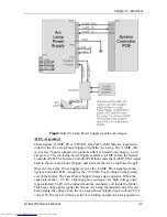
The Igniter has two functions: to light the Arc Lamp and to act as a link between
the Arc Lamp Power Supply and the Arc Lamp during normal Arc Lamp
operation. The Igniter contains the spark gap and the step-up transformer that
supplies the 32 kV pulse that lights the Arc Lamp. During lighting of the Arc
Lamp, the Arc Lamp Power Supply receives the /LAMP_ENA signal from the
System Controller PCB, it sends a +170 VDC boost voltage to the primary coil of
the Igniter. The Laser Power Supply charges up a capacitor. When the capacitor
reaches +5.5 kV, the spark gap arcs causing a very high voltage pulse
(approximately 32 kV) to be induced onto the Igniter Transformer step-up
(secondary) coil. The high voltage pulse goes to the Anode of the Arc Lamp. The
spark generated by the 32 kV pulse creates an arc inside the Xenon bulb that
ignites the Arc Lamp.
Содержание 250
Страница 16: ...Chapter 2 System Description Model 250 Service Manual 2 9 ...
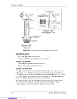
Страница 43: ...Chapter 4 Optical 4 10 Model 250 Service Manual Figure 4 6 Optical Path ...
Страница 55: ...Chapter 5 Optical 3 4 22 Model 100 Service Manual ...
Страница 85: ...Chapter 5 Electronics 5 30 Model 250 Service Manual Figure 5 19 Convergence Deflection PCB I O Diagram ...
Страница 86: ...Chapter 5 Electronics Model 250 Service Manual 5 31 Figure 5 20 Convergence Deflection PCB I O Diagram ...
Страница 91: ...Chapter 5 Electronics 5 36 Model 250 Service Manual Figure 5 22 Scan Reversal PCB I O Diagram ...
Страница 100: ...Chapter 5 Electronics Model 250 Service Manual 5 45 Figure 5 26 Video Amplifier PCB I O Diagram ...
Страница 131: ...Chapter 5 Electronics 5 76 Model 250 Service Manual Figure 5 44 Backplane Diagram right side ...
Страница 132: ...Chapter 5 Electronics Model 250 Service Manual 5 77 ...
Страница 138: ...Chapter 6 Miscellaneous Items 6 6 Model 250 Service Manual ...
Страница 166: ...Chapter 7 Troubleshooting 7 28 Model 250 Service Manual Figure 7 19 Backplane Diagram right side ...
Страница 167: ...Chapter 7 Troubleshooting Model 250 Service Manual 7 29 ...
Страница 181: ...Chapter 8 Software and Protocol 8 14 Model 250 Service Manual ...
Страница 185: ...Chapter 9 Parts List 9 4 Model 250 Service Manual ...

