Chapter 8---Software and Protocol
Model 250 Service Manual
8-5
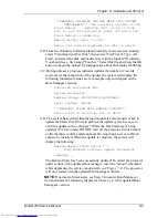
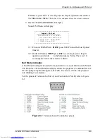
The software update is complete. To restart the projector, type in the “sys” or
“reboot” command and press Enter. The projector will now restart with the
updated System Software.
8.2 Importing/Exporting
Configuration
Data Export / Import Procedure - Rev 1.0.0
This appendix defines the steps to perform a Configuration Data Export & Import
from the Model 250 projector to a Host Computer. The Host Computer can be any
system that has RS232 download and upload capability, including an IBM-PC
compatible, an Apple MacIntosh, or a UNIX system. This paper describes the
procedures for an IBM-PC running the Windows 3.1 OS. We will use the
Windows “TERMINAL” application for communication with the projector. Other
Terminal emulation programs can be used (ProComm with Windows 95/98), but
all testing has been done with the TERMINAL application.
Note 1
: The TERMINAL application setup is the same as for controlling the
projector via an ANSI TERMINAL (see section 8-3 Terminals and Protocol).
Note 2:
Export/Import can be performed on either Port A or Port B. The Port
must be configured for ANSI Terminal. Port A speed is determined by DIP
SWITCH #4 on the System Controller board. UP is 9600 baud, DOWN is 19200
Baud. Port B can be configured for 2400, 9600 (default), or 19200 through the
Comm Setup Menu. If both Port A and Port B are ANSI Terminals, PORT A
must be used for Export/Import, so to use Port B, set Port A Device = None or
Switcher, Port B Device = ANSI.
Remember to Power Off (P) and HW RESET (Push RESET button -
figure 5-1 in Service Manual- or Circuit Breaker-on rear panel) after changing any
configuration parameters.
CAUTION
!
If you use 19200 Baud, your computer must
have a 16550 UART installed on the Comm Port. An unbuffered 8550
UART will lose data during EXPORT. This data loss cannot be detected
until a later IMPORT is attempted. Use 9600 if you are not sure. In all
cases use SOFTWARE FLOW CONTROL (XON/XOFF).
CAUTION
!
Laptop computer users must disable Advance
Power Management (APM) during an Export. APM power pulling causes
loss of data.
Содержание 250
Страница 16: ...Chapter 2 System Description Model 250 Service Manual 2 9 ...
Страница 43: ...Chapter 4 Optical 4 10 Model 250 Service Manual Figure 4 6 Optical Path ...
Страница 55: ...Chapter 5 Optical 3 4 22 Model 100 Service Manual ...
Страница 85: ...Chapter 5 Electronics 5 30 Model 250 Service Manual Figure 5 19 Convergence Deflection PCB I O Diagram ...
Страница 86: ...Chapter 5 Electronics Model 250 Service Manual 5 31 Figure 5 20 Convergence Deflection PCB I O Diagram ...
Страница 91: ...Chapter 5 Electronics 5 36 Model 250 Service Manual Figure 5 22 Scan Reversal PCB I O Diagram ...
Страница 100: ...Chapter 5 Electronics Model 250 Service Manual 5 45 Figure 5 26 Video Amplifier PCB I O Diagram ...
Страница 131: ...Chapter 5 Electronics 5 76 Model 250 Service Manual Figure 5 44 Backplane Diagram right side ...
Страница 132: ...Chapter 5 Electronics Model 250 Service Manual 5 77 ...
Страница 138: ...Chapter 6 Miscellaneous Items 6 6 Model 250 Service Manual ...
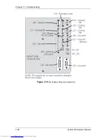
Страница 166: ...Chapter 7 Troubleshooting 7 28 Model 250 Service Manual Figure 7 19 Backplane Diagram right side ...
Страница 167: ...Chapter 7 Troubleshooting Model 250 Service Manual 7 29 ...
Страница 181: ...Chapter 8 Software and Protocol 8 14 Model 250 Service Manual ...
Страница 185: ...Chapter 9 Parts List 9 4 Model 250 Service Manual ...

