Chapter 4---Optical
4-12
Model 250 Service Manual
Positioner adjusts the light beam coming out of the Light Pipe so that it projects
squarely onto the face of the ILA
®
.
NOTE:
Do not adjust the XY Positioner unless there is a dark edge visible on
screen.
If the XY Positioner is misaligned, there will be a dark edge on the left, right, top
or bottom edge caused by the edge of the Light Pipe. Perform the Arc Lamp
alignment before adjusting the XY Positioner unless the dark edge makes Arc
Lamp alignment difficult or impossible.
To adjust the XY Positioner:
1.
Turn the projector ON and allow it to stabilize for at least 15 minutes.
2.
Check the screen for dark edges on the top, bottom, left, or right. Check
the screen with all three colors, using the Variable Flat Field (test pattern
#4) or with ILA
®
bias only. The dark edge will be obvious in either mode.
3.
Remove the front cover.
4.
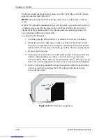
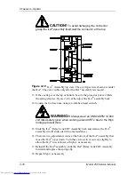
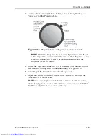
There are four access holes; two with small notches on the top of the hole
and two without notches (see Figure 4-8). Use the two access holes
without notches. These holes are for full aperture ILA
®
s. The upper access
hole is for vertical adjustment; the lower one is for horizontal adjustment.
5.
Insert a 3-mm (long shank) Hex-head wrench into either the horizontal or
vertical access hole and adjust the XY Positioner until the dark edge
moves off the screen.
Figure 4-8
XY Positioner adjust holes.
Содержание 250
Страница 16: ...Chapter 2 System Description Model 250 Service Manual 2 9 ...
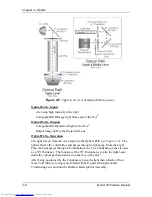
Страница 43: ...Chapter 4 Optical 4 10 Model 250 Service Manual Figure 4 6 Optical Path ...
Страница 55: ...Chapter 5 Optical 3 4 22 Model 100 Service Manual ...
Страница 85: ...Chapter 5 Electronics 5 30 Model 250 Service Manual Figure 5 19 Convergence Deflection PCB I O Diagram ...
Страница 86: ...Chapter 5 Electronics Model 250 Service Manual 5 31 Figure 5 20 Convergence Deflection PCB I O Diagram ...
Страница 91: ...Chapter 5 Electronics 5 36 Model 250 Service Manual Figure 5 22 Scan Reversal PCB I O Diagram ...
Страница 100: ...Chapter 5 Electronics Model 250 Service Manual 5 45 Figure 5 26 Video Amplifier PCB I O Diagram ...
Страница 131: ...Chapter 5 Electronics 5 76 Model 250 Service Manual Figure 5 44 Backplane Diagram right side ...
Страница 132: ...Chapter 5 Electronics Model 250 Service Manual 5 77 ...
Страница 138: ...Chapter 6 Miscellaneous Items 6 6 Model 250 Service Manual ...
Страница 166: ...Chapter 7 Troubleshooting 7 28 Model 250 Service Manual Figure 7 19 Backplane Diagram right side ...
Страница 167: ...Chapter 7 Troubleshooting Model 250 Service Manual 7 29 ...
Страница 181: ...Chapter 8 Software and Protocol 8 14 Model 250 Service Manual ...
Страница 185: ...Chapter 9 Parts List 9 4 Model 250 Service Manual ...


