Chapter 2---System Description
2-2
Model 250 Service Manual
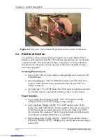
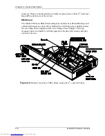
Figure 2-1
Overview of the Model 250 projector showing major components
2.2
Electrical Section
The electrical section consists of the Incoming Power Circuit, and the Power
Supplies and the Igniter Assembly. The following paragraphs give a list of major
components and a brief description of those components. For a more detailed
description of a component, refer to the chapter and section dedicated to that
particular component.
Incoming Power Circuit
!
Power Cord - The AC power comes in through the Power Cord to the AC
Circuit Breaker.
!
AC Circuit Breaker - The Circuit Breaker connects and disconnects the
projector from electrical energy and protects the projector from over-
voltage conditions.
!
AC Line Filter - The AC SF Series Line Filter reduces radiation generated
by a regulated power supply from returning to the AC power source.
Power Supplies
!
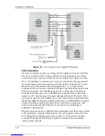
Low Voltage Power Supply (LVPS) - The LVPS supplies standby
voltages and the main system voltages to the projector.
!
Arc Lamp Power Supply (ALPS) - The ALPS supplies power to the
Igniter Assembly while the Arc Lamp is lighting. After the Arc Lamp has
lit, ALPS provides the steady state power to the Arc Lamp. The ALPS
also monitors the condition of the Arc Lamp and sends a feedback signal
to the System Controller PCB if there is a problem.
!
High Voltage Power Supply (HVPS) - The HVPS provides the Anode,
Focus (G
3
), Black Level (G
2
), Blanking (G
1
), and Dynamic Focus voltages
for the CRT.
Содержание 250
Страница 16: ...Chapter 2 System Description Model 250 Service Manual 2 9 ...
Страница 43: ...Chapter 4 Optical 4 10 Model 250 Service Manual Figure 4 6 Optical Path ...
Страница 55: ...Chapter 5 Optical 3 4 22 Model 100 Service Manual ...
Страница 85: ...Chapter 5 Electronics 5 30 Model 250 Service Manual Figure 5 19 Convergence Deflection PCB I O Diagram ...
Страница 86: ...Chapter 5 Electronics Model 250 Service Manual 5 31 Figure 5 20 Convergence Deflection PCB I O Diagram ...
Страница 91: ...Chapter 5 Electronics 5 36 Model 250 Service Manual Figure 5 22 Scan Reversal PCB I O Diagram ...
Страница 100: ...Chapter 5 Electronics Model 250 Service Manual 5 45 Figure 5 26 Video Amplifier PCB I O Diagram ...
Страница 131: ...Chapter 5 Electronics 5 76 Model 250 Service Manual Figure 5 44 Backplane Diagram right side ...
Страница 132: ...Chapter 5 Electronics Model 250 Service Manual 5 77 ...
Страница 138: ...Chapter 6 Miscellaneous Items 6 6 Model 250 Service Manual ...
Страница 166: ...Chapter 7 Troubleshooting 7 28 Model 250 Service Manual Figure 7 19 Backplane Diagram right side ...
Страница 167: ...Chapter 7 Troubleshooting Model 250 Service Manual 7 29 ...
Страница 181: ...Chapter 8 Software and Protocol 8 14 Model 250 Service Manual ...
Страница 185: ...Chapter 9 Parts List 9 4 Model 250 Service Manual ...


