Chapter 3---Electrical
3-14
Model 250 Service Manual
10.
Disconnect P45 (“Control”) at upper left of HVPS.
11.
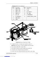
Disconnect and label the three Focus cables. The square tabs on these
cables (see Figure 3-6) may have to be lifted up. Gently pry up with a
small Flathead screwdriver.
12.
Remove all the cables from the slot in the cable guide located on the left
side of the HVPS.
13.
Verify that all plugs and cables are removed and out of the way so the
HVPS is free to be removed.
14.
Loosen (do not remove) the two Posi-drive screws (at the bottom of the
HVPS) that secure the HVPS metal housing to the projector.
15.
Remove the two Posi-drive screws that hold the top of the HVPS metal
housing to the projector frame.
16.
Grasp the HVPS at the bottom and lift upward and outward so that it slides
away from the bottom screws.
17.
Reinstall the High Voltage Power Supply in the reverse order.
NOTE
: When reinstalling the High Voltage Power Supply:
!
Make sure it slides over the bottom screws and the lip at the top of the
projector frame.
!
Make sure each anode cable “snaps” back into its receptacle. The
receptacles are about 2” inside the hole where the cable goes.
!
Make sure the rear flap on each focus cable connector snaps over the
square socket securely. Wiggle the connector a little to make it fits
securely.
18.
Replace the HVPS cover.
19.
Replace the projector covers.
20.
After replacing the HVPS, check and adjust Electronic Focus as necessary.
Содержание 250
Страница 16: ...Chapter 2 System Description Model 250 Service Manual 2 9 ...
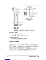
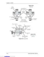
Страница 43: ...Chapter 4 Optical 4 10 Model 250 Service Manual Figure 4 6 Optical Path ...
Страница 55: ...Chapter 5 Optical 3 4 22 Model 100 Service Manual ...
Страница 85: ...Chapter 5 Electronics 5 30 Model 250 Service Manual Figure 5 19 Convergence Deflection PCB I O Diagram ...
Страница 86: ...Chapter 5 Electronics Model 250 Service Manual 5 31 Figure 5 20 Convergence Deflection PCB I O Diagram ...
Страница 91: ...Chapter 5 Electronics 5 36 Model 250 Service Manual Figure 5 22 Scan Reversal PCB I O Diagram ...
Страница 100: ...Chapter 5 Electronics Model 250 Service Manual 5 45 Figure 5 26 Video Amplifier PCB I O Diagram ...
Страница 131: ...Chapter 5 Electronics 5 76 Model 250 Service Manual Figure 5 44 Backplane Diagram right side ...
Страница 132: ...Chapter 5 Electronics Model 250 Service Manual 5 77 ...
Страница 138: ...Chapter 6 Miscellaneous Items 6 6 Model 250 Service Manual ...
Страница 166: ...Chapter 7 Troubleshooting 7 28 Model 250 Service Manual Figure 7 19 Backplane Diagram right side ...
Страница 167: ...Chapter 7 Troubleshooting Model 250 Service Manual 7 29 ...
Страница 181: ...Chapter 8 Software and Protocol 8 14 Model 250 Service Manual ...
Страница 185: ...Chapter 9 Parts List 9 4 Model 250 Service Manual ...


