Chapter 4---Optical
Model 250 Service Manual
4-17
19.
Retighten the two wing nuts and tighten the two hex nuts.
20.
Reset the ILA
®
biases to their previous levels from Step 2.
ILA
®
Back Focus Adjustment
The ILA
®
Back Focus adjustment moves the ILA
®
/Relay Lens/CRT assemblies
forward or backward as one unit to focus the ILA
®
output on the screen. When
using a zoom lens this adjustment allows the zoom lens’ tracking to remain
focused on the screen throughout the entire zoom range. Use the Focus Pattern
(Test Pattern #6) to perform this adjustment one color at a time. The procedures
below perform the ILA
®
Back Focus for the Green lens. The first procedure is for
a zoom lens. The second procedure is for a fixed lens.
For best results, perform ILA
®
Back Focus procedure with two people: One
person to stand in front of the screen to observe Spacer Balls and the other to
move the ILA
®
/Relay Lens/CRT assemblies back and forth. This is a factory-set
adjustment, but may need some touch-up in the field.
Tools Needed
4-mm Hex wrench
2.5-mm Hex wrench
Parts Needed
No parts are needed
To adjust the ILA
®
Back Focus for a Zoom Lens:
1.
Power the projector ON and allow to stabilize for at least 15 minutes
2.
Remove the Rear Cover and tilt up the Electronic Module.
3.
Hide Red and Blue. View Green.
4.
Select the Focus Pattern (Test Pattern #6).
5.
Select Projection Lens from the menu.
6.
Use the up/down arrow keys to zoom the Projection Lens to full telephoto
position (smallest image).
7.
Use left and right arrows to focus the projection lens to get sharply
focused spacer balls.
NOTE:
Spacer balls separate the layers inside the ILA
®
Assembly. They
are tiny, random, irregularly shaped spots that are visible throughout the
image. Stand directly in front of the screen and look in the lighter areas of
the image to see the Spacer balls. From throw distances shorter than 4
meters, spacer balls are difficult to see.
8.
Zoom the lens to a wide-angle position (largest image).
9.
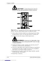
Loosen the wing nut on the Green Relay Lens (or whichever lens is being
focused).
Содержание 250
Страница 16: ...Chapter 2 System Description Model 250 Service Manual 2 9 ...
Страница 43: ...Chapter 4 Optical 4 10 Model 250 Service Manual Figure 4 6 Optical Path ...
Страница 55: ...Chapter 5 Optical 3 4 22 Model 100 Service Manual ...
Страница 85: ...Chapter 5 Electronics 5 30 Model 250 Service Manual Figure 5 19 Convergence Deflection PCB I O Diagram ...
Страница 86: ...Chapter 5 Electronics Model 250 Service Manual 5 31 Figure 5 20 Convergence Deflection PCB I O Diagram ...
Страница 91: ...Chapter 5 Electronics 5 36 Model 250 Service Manual Figure 5 22 Scan Reversal PCB I O Diagram ...
Страница 100: ...Chapter 5 Electronics Model 250 Service Manual 5 45 Figure 5 26 Video Amplifier PCB I O Diagram ...
Страница 131: ...Chapter 5 Electronics 5 76 Model 250 Service Manual Figure 5 44 Backplane Diagram right side ...
Страница 132: ...Chapter 5 Electronics Model 250 Service Manual 5 77 ...
Страница 138: ...Chapter 6 Miscellaneous Items 6 6 Model 250 Service Manual ...
Страница 166: ...Chapter 7 Troubleshooting 7 28 Model 250 Service Manual Figure 7 19 Backplane Diagram right side ...
Страница 167: ...Chapter 7 Troubleshooting Model 250 Service Manual 7 29 ...
Страница 181: ...Chapter 8 Software and Protocol 8 14 Model 250 Service Manual ...
Страница 185: ...Chapter 9 Parts List 9 4 Model 250 Service Manual ...

