Chapter 6---Miscellaneous Items
6-4
Model 250 Service Manual
6.4 Air
Filters
There are three polyurethane air filters in the Model 250. Air filters should be
cleaned whenever necessary. In extremely dusty or dirty conditions, the filters
should be cleaned more frequently. Remove the filters and vacuum them or blow
them clean with compressed air.
The air filters just slide out. No tools are required to remove and reinstall any of
the air filters. They are located as follows:
!
1 metal-framed filter in the rear of the projector in the bottom cover-
accessible when the rear cover is off.
!
1 filter on the bottom of the projector-slides out from the middle-left side
of the projector (grasp the hole in the filter frame). The filter can be peeled
off the Velcro on the frame, if necessary.
!
1 metal-framed filter in the front-left-bottom cover accessible with the
front cover off.
6.5 IR
Detectors
The IR Detectors receive command signals from the IR Remote Control. The
Model 250 projector has two IR Detectors, one on the front of the projector and
one on the rear (mounted on the System Controller PCB). The command signals
go to the System Controller PCB where they are distributed to the various PCBs,
typically by way of the IIC data bus. The IR Detectors can receive commands
from an IR Remote Control from a range of about 45-ft. line of sight.
6.6 EMI
Filter
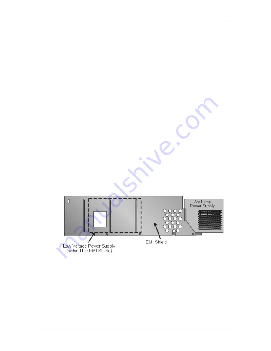
Figure 6-2
EMI Shield with Low Voltage Power Supply and Arc Lamp Power
Supply behind it
The purpose of the Electro-Magnetic Interference (EMI) Shield is to trap and
collect electromagnetic radiated fields generated by switching power supplies.
Switching power supplies radiate high frequency noise that may interfere with
radios, televisions, and other electronic appliances. The EMI Shield is constructed
of a special Mu metal that acts as an antenna to collect and ground the high
frequency noise as required by the Federal Communications Commission and
various other regulatory agencies.
Содержание 250
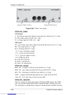
Страница 16: ...Chapter 2 System Description Model 250 Service Manual 2 9 ...
Страница 43: ...Chapter 4 Optical 4 10 Model 250 Service Manual Figure 4 6 Optical Path ...
Страница 55: ...Chapter 5 Optical 3 4 22 Model 100 Service Manual ...
Страница 85: ...Chapter 5 Electronics 5 30 Model 250 Service Manual Figure 5 19 Convergence Deflection PCB I O Diagram ...
Страница 86: ...Chapter 5 Electronics Model 250 Service Manual 5 31 Figure 5 20 Convergence Deflection PCB I O Diagram ...
Страница 91: ...Chapter 5 Electronics 5 36 Model 250 Service Manual Figure 5 22 Scan Reversal PCB I O Diagram ...
Страница 100: ...Chapter 5 Electronics Model 250 Service Manual 5 45 Figure 5 26 Video Amplifier PCB I O Diagram ...
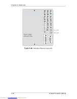
Страница 131: ...Chapter 5 Electronics 5 76 Model 250 Service Manual Figure 5 44 Backplane Diagram right side ...
Страница 132: ...Chapter 5 Electronics Model 250 Service Manual 5 77 ...
Страница 138: ...Chapter 6 Miscellaneous Items 6 6 Model 250 Service Manual ...
Страница 166: ...Chapter 7 Troubleshooting 7 28 Model 250 Service Manual Figure 7 19 Backplane Diagram right side ...
Страница 167: ...Chapter 7 Troubleshooting Model 250 Service Manual 7 29 ...
Страница 181: ...Chapter 8 Software and Protocol 8 14 Model 250 Service Manual ...
Страница 185: ...Chapter 9 Parts List 9 4 Model 250 Service Manual ...


