Chapter 5---Electronics
Model 250 Service Manual
5-41
10.
Recheck all Geometry and Convergence settings and readjust wherever
necessary.
11.
Replace the rear cover.
Front/Rear Projection Jumper Settings
In the procedures below each of the jumpers mentioned have a specific purpose:
J100 and J101 are the horizontal scanning jumpers, J 53 and J53A are the vertical
scanning jumpers, and J50 and J50A are the convergence jumpers.
CAUTION
!
Do not attempt to switch jumpers while the
projector is operating. The projector must be powered OFF when Scan
Reversal Jumpers are being changed.
Front/Rear Jumper Setting (Horizontal Reverse)
!
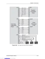
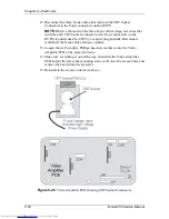
The Horizontal Scan Reversal Jumper reverses the image projection for
front or rear projection. Figure 5-25 illustrates the jumpers’ location on the
Scan Reversal Board.
!
The Model 250 Projector is shipped with the jumper plugs inserted in J50
and J100 for front/upright projection (see Table 5-1 for other
orientations).
To set the Horizontal Scan Jumper:
1.
Power off the projector by IR Remote or PC, and allow the cooling fans to
run until they shut off automatically).
2.
Turn the AC Circuit Breaker to the OFF position and unplug the AC
Power Cord.
3.
Remove the rear cover.
4.
Verify that the Horizontal Scan Reversal jumper is plugged into J100 and
the convergence jumper is plugged into J50 for front projection (see
Figure 5-25 and Table 5-1).
5.
Switch the Horizontal Scan Reversal jumper to J101 and the Convergence
Jumper to JA50 for rear projection (see Figure 5-25 and Table 5-1).
6.
Replace the projector cover.
7.
Power ON the projector and allow it to stabilize for a minimum of 15
minutes. It is recommended that the projector be operating for a least one
hour before performing shading adjustments.
8.
Recheck centering, convergence, and shading when changing jumpers for
front or rear screen projection.
Содержание 250
Страница 16: ...Chapter 2 System Description Model 250 Service Manual 2 9 ...
Страница 43: ...Chapter 4 Optical 4 10 Model 250 Service Manual Figure 4 6 Optical Path ...
Страница 55: ...Chapter 5 Optical 3 4 22 Model 100 Service Manual ...
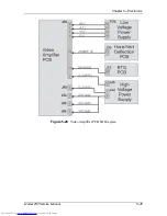
Страница 85: ...Chapter 5 Electronics 5 30 Model 250 Service Manual Figure 5 19 Convergence Deflection PCB I O Diagram ...
Страница 86: ...Chapter 5 Electronics Model 250 Service Manual 5 31 Figure 5 20 Convergence Deflection PCB I O Diagram ...
Страница 91: ...Chapter 5 Electronics 5 36 Model 250 Service Manual Figure 5 22 Scan Reversal PCB I O Diagram ...
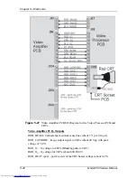
Страница 100: ...Chapter 5 Electronics Model 250 Service Manual 5 45 Figure 5 26 Video Amplifier PCB I O Diagram ...
Страница 131: ...Chapter 5 Electronics 5 76 Model 250 Service Manual Figure 5 44 Backplane Diagram right side ...
Страница 132: ...Chapter 5 Electronics Model 250 Service Manual 5 77 ...
Страница 138: ...Chapter 6 Miscellaneous Items 6 6 Model 250 Service Manual ...
Страница 166: ...Chapter 7 Troubleshooting 7 28 Model 250 Service Manual Figure 7 19 Backplane Diagram right side ...
Страница 167: ...Chapter 7 Troubleshooting Model 250 Service Manual 7 29 ...
Страница 181: ...Chapter 8 Software and Protocol 8 14 Model 250 Service Manual ...
Страница 185: ...Chapter 9 Parts List 9 4 Model 250 Service Manual ...

