Chapter 4---Optical
Model 250 Service Manual
4-9
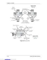
The Dichroic Beamsplitter Assembly separates the white light into its red, green,
and blue components. Each component light beam goes into the Prism Assembly
where it is polarized.
Light can be viewed as having two electromagnetic components: a Horizontal-
electric field and a Vertical-electric field. These fields are perpendicular to each
other. When unpolarized light travels through a polarizing beamsplitter, one of
these fields is reflected and one is transmitted or passes through the beamsplitter.
Upon striking the Prepolarizer, the Vertical field is reflected and is wasted, the P-
electric field is passed through the Prepolarizing Beamsplitter and continues on to
the Main Polarizer. The Main Polarizing Beamsplitter (PBS) is rotated 90
°
from
the Pre-Polarizing Beamsplitter so the Horizontal field that was transmitted
through the Prepolarizer is reflected by the Main Polarizer. The reflected
polarized light, either red, green or blue, leaves the PBS and goes directly into the
ILA
®
(see Figure 4-6 and Figure 4-7).
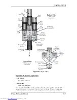
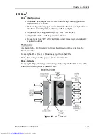
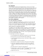
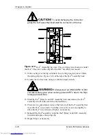
Each color exits the Prism Assembly and enters an ILA
®
where the Liquid Crystal
in the ILA
®
rotates the polarized light. The image light striking the input side of
the ILA
®
modulates the polarized light. The image on the input of the ILA
®
originates as a image signal and is transformed into an image by the CRT. The
image from the CRT passes through the Relay Lens and is focused onto the input
side of the ILA
®
. The modulated image light leaves the output side of the ILA
®
and re-enters the Prism Assembly where all three colors combine in the 4P
combining optic. The image light exits the Prism Assembly, passes through the
Projection Lens, and is projected out on the screen (see Figure 4-7).
WARNING!!!
Wear safety goggles (rated X5) when
working anywhere near the light path from the arc lamp or the projection
lens.
DO NOT open any of the Optical Support Assembly covers while the
projector is ON. The bright light can cause severe eye damage.
Содержание 250
Страница 16: ...Chapter 2 System Description Model 250 Service Manual 2 9 ...
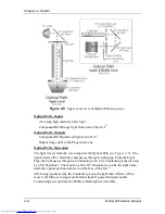
Страница 43: ...Chapter 4 Optical 4 10 Model 250 Service Manual Figure 4 6 Optical Path ...
Страница 55: ...Chapter 5 Optical 3 4 22 Model 100 Service Manual ...
Страница 85: ...Chapter 5 Electronics 5 30 Model 250 Service Manual Figure 5 19 Convergence Deflection PCB I O Diagram ...
Страница 86: ...Chapter 5 Electronics Model 250 Service Manual 5 31 Figure 5 20 Convergence Deflection PCB I O Diagram ...
Страница 91: ...Chapter 5 Electronics 5 36 Model 250 Service Manual Figure 5 22 Scan Reversal PCB I O Diagram ...
Страница 100: ...Chapter 5 Electronics Model 250 Service Manual 5 45 Figure 5 26 Video Amplifier PCB I O Diagram ...
Страница 131: ...Chapter 5 Electronics 5 76 Model 250 Service Manual Figure 5 44 Backplane Diagram right side ...
Страница 132: ...Chapter 5 Electronics Model 250 Service Manual 5 77 ...
Страница 138: ...Chapter 6 Miscellaneous Items 6 6 Model 250 Service Manual ...
Страница 166: ...Chapter 7 Troubleshooting 7 28 Model 250 Service Manual Figure 7 19 Backplane Diagram right side ...
Страница 167: ...Chapter 7 Troubleshooting Model 250 Service Manual 7 29 ...
Страница 181: ...Chapter 8 Software and Protocol 8 14 Model 250 Service Manual ...
Страница 185: ...Chapter 9 Parts List 9 4 Model 250 Service Manual ...


