Chapter 5---Electronics
Model 250 Service Manual
5-51
5.10 CRT/Yoke Assemblies
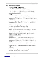
CRT/Yoke Assemblies - Main Function
!
CRTs converts image signal to image light
!
Yokes provide horizontal and vertical deflection for CRTs
!
Yokes provide x-axis and y-axis convergence correction for CRTs
CRT/Yoke Assemblies - Inputs
To Yokes
H_RGB_YOKE (pos.) - top of red, green, and blue horizontal yokes.
V_RGB_YOKE (pos.) - top of red, green, and blue vertical yokes.
RGB_LOCK (pos.) - interlock for red, green, and blue yokes (5 V when closed or
15 V when open).
X_RGB_YOKE (pos.) - top of red, green, and blue X-axis Convergence yokes.
Y_RGB_YOKE (pos.) - top of red, green, and blue Y-axis Convergence yokes.
To CRTs
Anode Voltage from High Voltage Power Supply (25 kV).
Focus Voltage from High Voltage Power Supply (7 kV).
RGB G
1
-
G
1
grid signal from Video Amplifier PCB.
RGB G2 - G2 supply voltage from Video Amplifier PCB (about 600-800 V).
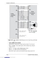
RGB_CATHODE - video output signal from the Video Amplifier PCB (about 40
Vpp with a peak voltage of about 70 V).
RGB_HEAT (pos.) - positive side of CRTs heater voltage (about 6.2 V).
CRT/Yoke Assemblies - Output
From Yokes
H_RGB_YOKE (neg.) - bottom of red, green, and blue horizontal yokes.
V_RGB_YOKE (neg.)- bottom of red, green, and blue vertical yokes.
RGB_LOCK (neg.) - interlock for red, green, and blue yokes (5 V when closed or
0 V when open).
X_RGB_YOKE (neg.) - bottom of red, green, and blue X-axis Convergence
yokes.
Y_RGB_YOKE (neg.) - bottom of red, green, and blue Y-axis Convergence
yokes.
From CRTs
RGB_HEAT (neg.) - negative side of CRTs heater voltage (0 V).
ARC_GND - CRTs ground (Anode supply return line).
Содержание 250
Страница 16: ...Chapter 2 System Description Model 250 Service Manual 2 9 ...
Страница 43: ...Chapter 4 Optical 4 10 Model 250 Service Manual Figure 4 6 Optical Path ...
Страница 55: ...Chapter 5 Optical 3 4 22 Model 100 Service Manual ...
Страница 85: ...Chapter 5 Electronics 5 30 Model 250 Service Manual Figure 5 19 Convergence Deflection PCB I O Diagram ...
Страница 86: ...Chapter 5 Electronics Model 250 Service Manual 5 31 Figure 5 20 Convergence Deflection PCB I O Diagram ...
Страница 91: ...Chapter 5 Electronics 5 36 Model 250 Service Manual Figure 5 22 Scan Reversal PCB I O Diagram ...
Страница 100: ...Chapter 5 Electronics Model 250 Service Manual 5 45 Figure 5 26 Video Amplifier PCB I O Diagram ...
Страница 131: ...Chapter 5 Electronics 5 76 Model 250 Service Manual Figure 5 44 Backplane Diagram right side ...
Страница 132: ...Chapter 5 Electronics Model 250 Service Manual 5 77 ...
Страница 138: ...Chapter 6 Miscellaneous Items 6 6 Model 250 Service Manual ...
Страница 166: ...Chapter 7 Troubleshooting 7 28 Model 250 Service Manual Figure 7 19 Backplane Diagram right side ...
Страница 167: ...Chapter 7 Troubleshooting Model 250 Service Manual 7 29 ...
Страница 181: ...Chapter 8 Software and Protocol 8 14 Model 250 Service Manual ...
Страница 185: ...Chapter 9 Parts List 9 4 Model 250 Service Manual ...


