Chapter 7---Troubleshooting
7-4
Model 250 Service Manual
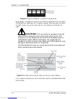
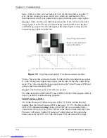
Figure 7-2
Dip Switch Block on System Controller PCB.
Reset Switch - The Reset Switch resets the CPU if the projector locks up and does
not respond to an IR Remote, PC or Laptop computer. If the rear panel is in place,
the CPU can also be reset by cycling the AC Circuit Breaker off and back on
again.
CAUTION!
If the Arc Lamp was operating or recently
turned off (the cooling fans were still running) at the time the CPU
locked up, it is very important to turn the AC Circuit Breaker back on
immediately to power ON the cooling fans. The cooling fans are
needed to cool down the Arc Lamp, Optics and PCBs properly to avoid
damage to optical and electronic components.
If the Reset Switch is used, the cooling fans will stop momentarily and
begin operating again automatically.
Figure 7-3
LEDs visible from the left side of the Electronics Module.
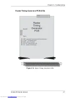
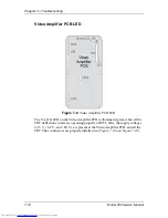
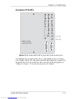
For a complete description on each of the LEDs, check the individual PCBs LEDs
in this section.
Содержание 250
Страница 16: ...Chapter 2 System Description Model 250 Service Manual 2 9 ...
Страница 43: ...Chapter 4 Optical 4 10 Model 250 Service Manual Figure 4 6 Optical Path ...
Страница 55: ...Chapter 5 Optical 3 4 22 Model 100 Service Manual ...
Страница 85: ...Chapter 5 Electronics 5 30 Model 250 Service Manual Figure 5 19 Convergence Deflection PCB I O Diagram ...
Страница 86: ...Chapter 5 Electronics Model 250 Service Manual 5 31 Figure 5 20 Convergence Deflection PCB I O Diagram ...
Страница 91: ...Chapter 5 Electronics 5 36 Model 250 Service Manual Figure 5 22 Scan Reversal PCB I O Diagram ...
Страница 100: ...Chapter 5 Electronics Model 250 Service Manual 5 45 Figure 5 26 Video Amplifier PCB I O Diagram ...
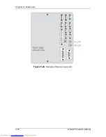
Страница 131: ...Chapter 5 Electronics 5 76 Model 250 Service Manual Figure 5 44 Backplane Diagram right side ...
Страница 132: ...Chapter 5 Electronics Model 250 Service Manual 5 77 ...
Страница 138: ...Chapter 6 Miscellaneous Items 6 6 Model 250 Service Manual ...
Страница 166: ...Chapter 7 Troubleshooting 7 28 Model 250 Service Manual Figure 7 19 Backplane Diagram right side ...
Страница 167: ...Chapter 7 Troubleshooting Model 250 Service Manual 7 29 ...
Страница 181: ...Chapter 8 Software and Protocol 8 14 Model 250 Service Manual ...
Страница 185: ...Chapter 9 Parts List 9 4 Model 250 Service Manual ...


