Chapter 4---Optical
Model 250 Service Manual
4-5
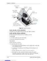
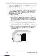
Figure 4-3
Arc Lamp Assembly access door.
Arc Lamp - Remove and Replace
The Arc Lamp Enclosure Assembly consists of the Xenon Arc Lamp module and
blower. Replace the blower together with the Arc Lamp Module.
Tools Needed
7/16 inch wrench
#1 Pozi-drive Phillips-head screwdriver
Diagonal wire cutters (or equivalent)
Parts Needed
Arc Lamp p/n 106298
WARNING!!!
Dangerously bright light and high current
exist in this area of the projector. Before proceeding with the removal of
any subassemblies below, verify that the circuit breaker at the rear of the
projector is turned off and the power plug is removed from the AC outlet.
To Remove the Arc Lamp:
1.
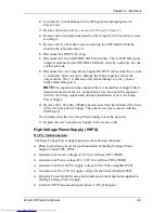
Power off the projector by IR Remote or PC, and allow the cooling fans to
run until they shut off.
2.
Turn the AC Circuit Breaker to the OFF position but leave the AC Power
Cord plugged in to maintain chassis ground.
3.
Remove the front cover (see Section 6.1).
4.
Disconnect the white Anode cable from the Igniter, using the 7/16-inch
wrench (see Figure 3-7).
Содержание 250
Страница 16: ...Chapter 2 System Description Model 250 Service Manual 2 9 ...
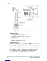
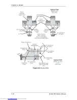
Страница 43: ...Chapter 4 Optical 4 10 Model 250 Service Manual Figure 4 6 Optical Path ...
Страница 55: ...Chapter 5 Optical 3 4 22 Model 100 Service Manual ...
Страница 85: ...Chapter 5 Electronics 5 30 Model 250 Service Manual Figure 5 19 Convergence Deflection PCB I O Diagram ...
Страница 86: ...Chapter 5 Electronics Model 250 Service Manual 5 31 Figure 5 20 Convergence Deflection PCB I O Diagram ...
Страница 91: ...Chapter 5 Electronics 5 36 Model 250 Service Manual Figure 5 22 Scan Reversal PCB I O Diagram ...
Страница 100: ...Chapter 5 Electronics Model 250 Service Manual 5 45 Figure 5 26 Video Amplifier PCB I O Diagram ...
Страница 131: ...Chapter 5 Electronics 5 76 Model 250 Service Manual Figure 5 44 Backplane Diagram right side ...
Страница 132: ...Chapter 5 Electronics Model 250 Service Manual 5 77 ...
Страница 138: ...Chapter 6 Miscellaneous Items 6 6 Model 250 Service Manual ...
Страница 166: ...Chapter 7 Troubleshooting 7 28 Model 250 Service Manual Figure 7 19 Backplane Diagram right side ...
Страница 167: ...Chapter 7 Troubleshooting Model 250 Service Manual 7 29 ...
Страница 181: ...Chapter 8 Software and Protocol 8 14 Model 250 Service Manual ...
Страница 185: ...Chapter 9 Parts List 9 4 Model 250 Service Manual ...


