Chapter 3---Electrical
3-8
Model 250 Service Manual
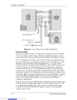
The Arc Lamp Power Supply sends the
/LAMP_LIT signal back to the System Controller when the Arc Lamp is lit.
The Arc Lamp regulates its output to give a constant Arc Lamp power. If the Arc
Lamp has not lit within 20 seconds (/LAMP_LIT still high), the System
Controller PCB will try once more to re-initiate the sequence. If the Arc Lamp
still fails to light, an error code will appear on the back panel (see section 7.22
Error Codes).
The Arc Lamp Power Supply negative output goes to the Cathode of the Arc
Lamp. The positive output goes to the Anode of the Arc Lamp and is tied to
chassis ground.
The Arc Lamp Power Supply is shielded electrically and magnetically to prevent
noise or disturbances in the CRTs or other circuitry.
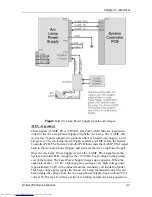
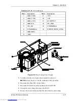
Figure 3-3
Arc Lamp Power Supply connections.
ALPS - Service Adjustments
The Arc Lamp Power Supply for the Model 250 is preset at the factory and does
not have any Service Adjustments. The output is programmed for a constant
2 kW. Arc Lamp replacement does not require any electrical readjustments.
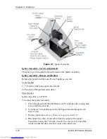
ALPS - Remove and Replace
Tools Needed
#2 Pozi-drive Phillips-head screwdriver
Parts Needed
Arc Lamp Power Supply p/n - 105216
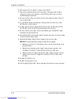
To remove the Arc Lamp Power Supply (ALPS):
1.
Power off the projector by IR Remote or PC, and allow the cooling fans to
run until they shut off.
Содержание 250
Страница 16: ...Chapter 2 System Description Model 250 Service Manual 2 9 ...
Страница 43: ...Chapter 4 Optical 4 10 Model 250 Service Manual Figure 4 6 Optical Path ...
Страница 55: ...Chapter 5 Optical 3 4 22 Model 100 Service Manual ...
Страница 85: ...Chapter 5 Electronics 5 30 Model 250 Service Manual Figure 5 19 Convergence Deflection PCB I O Diagram ...
Страница 86: ...Chapter 5 Electronics Model 250 Service Manual 5 31 Figure 5 20 Convergence Deflection PCB I O Diagram ...
Страница 91: ...Chapter 5 Electronics 5 36 Model 250 Service Manual Figure 5 22 Scan Reversal PCB I O Diagram ...
Страница 100: ...Chapter 5 Electronics Model 250 Service Manual 5 45 Figure 5 26 Video Amplifier PCB I O Diagram ...
Страница 131: ...Chapter 5 Electronics 5 76 Model 250 Service Manual Figure 5 44 Backplane Diagram right side ...
Страница 132: ...Chapter 5 Electronics Model 250 Service Manual 5 77 ...
Страница 138: ...Chapter 6 Miscellaneous Items 6 6 Model 250 Service Manual ...
Страница 166: ...Chapter 7 Troubleshooting 7 28 Model 250 Service Manual Figure 7 19 Backplane Diagram right side ...
Страница 167: ...Chapter 7 Troubleshooting Model 250 Service Manual 7 29 ...
Страница 181: ...Chapter 8 Software and Protocol 8 14 Model 250 Service Manual ...
Страница 185: ...Chapter 9 Parts List 9 4 Model 250 Service Manual ...

