Chapter 5---Electronics
Model 250 Service Manual
5-11
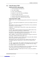
5.4 Video Processor PCB
Video Processor PCB - Main Functions
!
Video signal input and multiplexing
!
Sync signal stripping
!
Overlay signal multiplexing
!
Brightness, Contrast, DC Restore and Blanking
!
Video signal gamma correction
!
Sensitivity and Threshold signal input and control
!
Automatic Contrast, G2, and internal image limiting
Video Processor PCB - Inputs
RGBHV VIC 1,2, & 3 - External image signals from the VICs for red, green, and
blue.
/SEL_VIC - input signal from the RGB VIC used to select the input source from
VIC #1.
RGB_OVER - from the System Controller PCB, the Menu overlays and internal
test patterns for red, green, and blue.
OVERLAY - from the System Controller PCB, switches between internal and
external sources.
CLAMP - Pulse signal from the Raster Timing Generator PCB, tells the Video
Processor PCB the timing and duration of the DC Restore.
BLANKING - Pulse signal from the Raster Timing Generator PCB, it tells the
Video Processor PCB the blanking interval during the scan.
RGB_THRESH - Threshold correction information for red, green, or blue from
the System Controller PCB. Real time data at 0-1 V.
RGB_SENS - Sensitivity correction information for red, green or blue from the
System Controller PCB. Real time data at 0-1 V.
RGB_BEAM - sense signal proportional to the cathode current averaged over
several horizontal lines in the red, green, or blue CRT. The voltage level is +
mV/mA.
/VA_OK - signal from the Video Amplifier PCB telling the Video Processor PCB
the Video Amplifier PCB is receiving red, green, and blue deflections voltages
from the Horizontal Vertical Deflection PCB.
IIC_DATA - IIC data line. Bi-directional serial line for synchronous data transfer
between the System Controller PCB and Video Processor PCB.
IIC_CLK - IIC clock line. Unidirectional clock line for control of synchronous
data transfer over IIC bus.
Содержание 250
Страница 16: ...Chapter 2 System Description Model 250 Service Manual 2 9 ...
Страница 43: ...Chapter 4 Optical 4 10 Model 250 Service Manual Figure 4 6 Optical Path ...
Страница 55: ...Chapter 5 Optical 3 4 22 Model 100 Service Manual ...
Страница 85: ...Chapter 5 Electronics 5 30 Model 250 Service Manual Figure 5 19 Convergence Deflection PCB I O Diagram ...
Страница 86: ...Chapter 5 Electronics Model 250 Service Manual 5 31 Figure 5 20 Convergence Deflection PCB I O Diagram ...
Страница 91: ...Chapter 5 Electronics 5 36 Model 250 Service Manual Figure 5 22 Scan Reversal PCB I O Diagram ...
Страница 100: ...Chapter 5 Electronics Model 250 Service Manual 5 45 Figure 5 26 Video Amplifier PCB I O Diagram ...
Страница 131: ...Chapter 5 Electronics 5 76 Model 250 Service Manual Figure 5 44 Backplane Diagram right side ...
Страница 132: ...Chapter 5 Electronics Model 250 Service Manual 5 77 ...
Страница 138: ...Chapter 6 Miscellaneous Items 6 6 Model 250 Service Manual ...
Страница 166: ...Chapter 7 Troubleshooting 7 28 Model 250 Service Manual Figure 7 19 Backplane Diagram right side ...
Страница 167: ...Chapter 7 Troubleshooting Model 250 Service Manual 7 29 ...
Страница 181: ...Chapter 8 Software and Protocol 8 14 Model 250 Service Manual ...
Страница 185: ...Chapter 9 Parts List 9 4 Model 250 Service Manual ...

