Chapter 8---Software and Protocol
Model 250 Service Manual
8-11
Communications Protocol
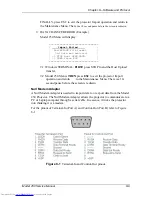
Select SETTINGS using the menu bar, then select COMMUNICATIONS. Set the
following communications parameters and modes.
Table 8-2
Communications settings
Baud Rate
9600
Stop Bits
1
Data Bits
8
Flow Control
Xon/Xoff
Parity
None
Carrier Detect
No
Parity Check
No
Connector
Com1-This is PC
configuration
dependent.
Select FILE from the menu bar and select NEW. Under File Name enter VT-
100.TRM. This will allow the user to select the file VT-100.TRM with the
above parameters saved for future use.
Table 8-3
VT-100 Terminal and Remote Command Equivalents
Action
Keyboard
Input
Executive
Remote Keys
Service
Remote Keys
Dec.
Hex.
Power OFF
(All)
CTRL + F
6
6
Power ON (All)
CTRL + U
21
15
Power ON/OFF
CTRL-P
POWER
POWER
16
10
Power
ON/OFF-
Electronics only
CTRL + E
5
5
Power ON/OFF
Lamp
CTRL + L
12
0C
Left Arrow
Left Arrow
Left Arrow
Left Arrow
27 91
68*
1B 5B
44*
Right Arrow
Right Arrow
Right Arrow
Right Arrow
27 91
67*
1B 5B
43*
Up Arrow
Up Arrow
Up Arrow
Up Arrow
27 91
65*
1B 5B
41*
Down Arrow
Down Arrow
Down Arrow
Down Arrow
27 91
66*
1B 5B
42*
Back out of
menu
Esc
ESC
ESC
27
1B
Blanking
B
BLANK
66
42
Bow, H & V
U
BOW
85
55
Brightness
I
BRT
BRT
73
49
Содержание 250
Страница 16: ...Chapter 2 System Description Model 250 Service Manual 2 9 ...
Страница 43: ...Chapter 4 Optical 4 10 Model 250 Service Manual Figure 4 6 Optical Path ...
Страница 55: ...Chapter 5 Optical 3 4 22 Model 100 Service Manual ...
Страница 85: ...Chapter 5 Electronics 5 30 Model 250 Service Manual Figure 5 19 Convergence Deflection PCB I O Diagram ...
Страница 86: ...Chapter 5 Electronics Model 250 Service Manual 5 31 Figure 5 20 Convergence Deflection PCB I O Diagram ...
Страница 91: ...Chapter 5 Electronics 5 36 Model 250 Service Manual Figure 5 22 Scan Reversal PCB I O Diagram ...
Страница 100: ...Chapter 5 Electronics Model 250 Service Manual 5 45 Figure 5 26 Video Amplifier PCB I O Diagram ...
Страница 131: ...Chapter 5 Electronics 5 76 Model 250 Service Manual Figure 5 44 Backplane Diagram right side ...
Страница 132: ...Chapter 5 Electronics Model 250 Service Manual 5 77 ...
Страница 138: ...Chapter 6 Miscellaneous Items 6 6 Model 250 Service Manual ...
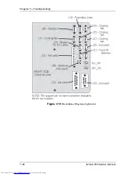
Страница 166: ...Chapter 7 Troubleshooting 7 28 Model 250 Service Manual Figure 7 19 Backplane Diagram right side ...
Страница 167: ...Chapter 7 Troubleshooting Model 250 Service Manual 7 29 ...
Страница 181: ...Chapter 8 Software and Protocol 8 14 Model 250 Service Manual ...
Страница 185: ...Chapter 9 Parts List 9 4 Model 250 Service Manual ...

