Chapter 5---Electronics
Model 250 Service Manual
5-69
interface. An operator selects the VIC and input in the Channels Menu (see
section 4-6 in the User’s Guide).
The YPbPr VIC strips the sync pulses that are combined with the green image
signal (Y in YPbPr mode) and sends them to the Video Processor PCB as a
composite sync signal (H_SYNC). The Video Processor PCB separates the
composite sync signal and sends it to the Raster Timing Generator PCB.
The YPbPr VIC also does signal processing in the YPbPr mode with the Tint,
Color, and Sharpness options in the Picture Menu. The Tint control adjusts the
tint of the colors displayed. Facial tones will vary from slightly green at zero to
slightly red at 255. The Color control adjusts the amount of color saturation or
color intensity. Colors will be almost grayscale at zero and very saturated at 255.
The Sharpness control adjusts the high frequency peaking of the black and white
details. These options are not available and are disabled in the RGB mode.
The YPbPr VIC has two LEDs. The RGB LED illuminates green when the
YPbPr_VIC is in RGB input mode. The YPbPr LED illuminates green when the
YPbPr_VIC is in YPbPr input mode. Only one LED will be illuminated at one
time. Neither LED is illuminated when the YPbPr_VIC is not selected as the input
to projector.
YPbPr VIC - Service Adjustments
There are no physical service adjustments to the YPbPr VIC
YPbPr VIC - Remove and Replace
Tools Needed
#0 Pozi-drive Phillips-head screwdriver
Parts Needed
YPbPr VIC p/n 106340
To remove the YPbPr VIC:
1.
Power off the projector by IR Remote or PC, and allow the cooling fans to
run until they shut off automatically.
2.
Turn the AC Circuit Breaker to the OFF position and unplug the AC
Power Cord.
3.
It is not necessary to remove the rear cover.
4.
Disconnect the input BNC cables from the VIC.
5.
Remove the two retaining screws from the faceplate of the VIC.
6.
Pull the VIC out of the Electronics Module.
7.
Reverse the process to install the VIC.
Содержание 250
Страница 16: ...Chapter 2 System Description Model 250 Service Manual 2 9 ...
Страница 43: ...Chapter 4 Optical 4 10 Model 250 Service Manual Figure 4 6 Optical Path ...
Страница 55: ...Chapter 5 Optical 3 4 22 Model 100 Service Manual ...
Страница 85: ...Chapter 5 Electronics 5 30 Model 250 Service Manual Figure 5 19 Convergence Deflection PCB I O Diagram ...
Страница 86: ...Chapter 5 Electronics Model 250 Service Manual 5 31 Figure 5 20 Convergence Deflection PCB I O Diagram ...
Страница 91: ...Chapter 5 Electronics 5 36 Model 250 Service Manual Figure 5 22 Scan Reversal PCB I O Diagram ...
Страница 100: ...Chapter 5 Electronics Model 250 Service Manual 5 45 Figure 5 26 Video Amplifier PCB I O Diagram ...
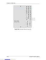
Страница 131: ...Chapter 5 Electronics 5 76 Model 250 Service Manual Figure 5 44 Backplane Diagram right side ...
Страница 132: ...Chapter 5 Electronics Model 250 Service Manual 5 77 ...
Страница 138: ...Chapter 6 Miscellaneous Items 6 6 Model 250 Service Manual ...
Страница 166: ...Chapter 7 Troubleshooting 7 28 Model 250 Service Manual Figure 7 19 Backplane Diagram right side ...
Страница 167: ...Chapter 7 Troubleshooting Model 250 Service Manual 7 29 ...
Страница 181: ...Chapter 8 Software and Protocol 8 14 Model 250 Service Manual ...
Страница 185: ...Chapter 9 Parts List 9 4 Model 250 Service Manual ...

