Chapter 3---Electrical
Model 250 Service Manual
3-13
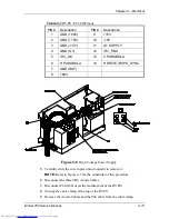
Table 3-1
HVPS -
P45 I/O Pinout
PIN #
Description
PIN #
Description
1
GND (+80V)
9
+15V
2
GND (+15V)
10
-15V
3
GND (-15V)
11
G1 SUPPLY
4
GND (G1)
12
/HV_ENA
5
/HV_OK
13
V PARABOLA
6
H PARABOLA
14
H DRIVE (HVPS_SYNC
7
GND (DAF)
8
+80V
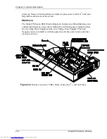
Figure 3-6
High Voltage Power Supply.
5.
Carefully slide the cover upward and outward to remove it.
NOTE
: Refer to Figure 4-5 for the remainder of this procedure.
6.
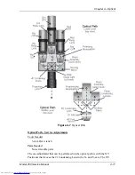
Disconnect the three CRT Anode Cables.
7.
Disconnect P44-G2 Out (at the middle-front of the HVPS).
8.
Unsnap the cable clamp at the top of the HVPS.
9.
Remove the Anode Cables and the P44 cable from the cable clamp.
Содержание 250
Страница 16: ...Chapter 2 System Description Model 250 Service Manual 2 9 ...
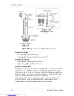
Страница 43: ...Chapter 4 Optical 4 10 Model 250 Service Manual Figure 4 6 Optical Path ...
Страница 55: ...Chapter 5 Optical 3 4 22 Model 100 Service Manual ...
Страница 85: ...Chapter 5 Electronics 5 30 Model 250 Service Manual Figure 5 19 Convergence Deflection PCB I O Diagram ...
Страница 86: ...Chapter 5 Electronics Model 250 Service Manual 5 31 Figure 5 20 Convergence Deflection PCB I O Diagram ...
Страница 91: ...Chapter 5 Electronics 5 36 Model 250 Service Manual Figure 5 22 Scan Reversal PCB I O Diagram ...
Страница 100: ...Chapter 5 Electronics Model 250 Service Manual 5 45 Figure 5 26 Video Amplifier PCB I O Diagram ...
Страница 131: ...Chapter 5 Electronics 5 76 Model 250 Service Manual Figure 5 44 Backplane Diagram right side ...
Страница 132: ...Chapter 5 Electronics Model 250 Service Manual 5 77 ...
Страница 138: ...Chapter 6 Miscellaneous Items 6 6 Model 250 Service Manual ...
Страница 166: ...Chapter 7 Troubleshooting 7 28 Model 250 Service Manual Figure 7 19 Backplane Diagram right side ...
Страница 167: ...Chapter 7 Troubleshooting Model 250 Service Manual 7 29 ...
Страница 181: ...Chapter 8 Software and Protocol 8 14 Model 250 Service Manual ...
Страница 185: ...Chapter 9 Parts List 9 4 Model 250 Service Manual ...

