Chapter 6---Miscellaneous Items
Model 250 Service Manual
6-5
The EMI Shield is a metal plate located in front of the Low Voltage Power
Supply and the Arc Lamp Power Supply. It must be removed before removing
either of these power supplies. Be sure to replace the EMI Shield after replacing
either the Low Voltage Power Supply or the Low Voltage Power Supply.
6.7 Cleaning Lenses, ILA
®
Assemblies and Mirrors
The projection lens is the only item that requires periodic cleaning. Other
assemblies are covered to prevent dust entering or finger smudging. Cleaning may
be needed for special circumstances such as replacing an assembly. Cleaning
should only require removing excessive dust (use canned air such as “Office
Duster” or "Aero Duster") or removing fingerprint smudges (use “Kodak Lens
paper”, or equivalent) from the projection lens. As much as possible, clean the
optics only when absolutely necessary.
Projection Lens - Use lens paper and wipe the lens clean in a vertical motion from
top to bottom. Use compressed air to blow excess dust from the lens. An optical
lens cleaning solution can also be used to remove finger smudges.
ILA
®
Assembly - Clean the ILA
®
assembly faces with compressed air only. Do
not wipe the ILA assembly faces.
CRT Faces - Use compressed air to blow dust off and lens paper to clean face.
Relay Lens - Same as Projection Lens.
Mirrors and Polarizing Beam Splitter Windows - The Optical Shields cover the
Dichroic Mirror Assembly and Polarizing Beam Splitter windows. Normally
cleaning is not needed. Clean only if absolutely necessary using compressed air.
Do not wipe mirrors.
Содержание 250
Страница 16: ...Chapter 2 System Description Model 250 Service Manual 2 9 ...
Страница 43: ...Chapter 4 Optical 4 10 Model 250 Service Manual Figure 4 6 Optical Path ...
Страница 55: ...Chapter 5 Optical 3 4 22 Model 100 Service Manual ...
Страница 85: ...Chapter 5 Electronics 5 30 Model 250 Service Manual Figure 5 19 Convergence Deflection PCB I O Diagram ...
Страница 86: ...Chapter 5 Electronics Model 250 Service Manual 5 31 Figure 5 20 Convergence Deflection PCB I O Diagram ...
Страница 91: ...Chapter 5 Electronics 5 36 Model 250 Service Manual Figure 5 22 Scan Reversal PCB I O Diagram ...
Страница 100: ...Chapter 5 Electronics Model 250 Service Manual 5 45 Figure 5 26 Video Amplifier PCB I O Diagram ...
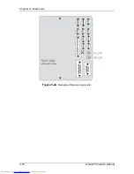
Страница 131: ...Chapter 5 Electronics 5 76 Model 250 Service Manual Figure 5 44 Backplane Diagram right side ...
Страница 132: ...Chapter 5 Electronics Model 250 Service Manual 5 77 ...
Страница 138: ...Chapter 6 Miscellaneous Items 6 6 Model 250 Service Manual ...
Страница 166: ...Chapter 7 Troubleshooting 7 28 Model 250 Service Manual Figure 7 19 Backplane Diagram right side ...
Страница 167: ...Chapter 7 Troubleshooting Model 250 Service Manual 7 29 ...
Страница 181: ...Chapter 8 Software and Protocol 8 14 Model 250 Service Manual ...
Страница 185: ...Chapter 9 Parts List 9 4 Model 250 Service Manual ...

