Chapter 3
Preparing Superdome for Booting
Setting Up the CE Tool (PC)
58
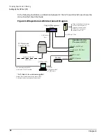
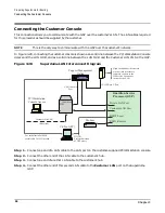
In the following illustration, a dotted line between CE Tool (PC) and RS-232 Local shows the
connection that should be made:
Figure 3-22Superdome LAN Interconnect Diagram
PC/Workstation
Console Access
NOTE:
Preferred method
of GSP access
CE Tool (PC)
For initial install of SMS,
serial cable 24542G needed.
Dashed lines indicate temporary connections.
Solid lines indicate permanent connections.
*LAN hubs to be customer supplied
Customer Site LAN
(if desired)
Modem
Private LAN Port
Customer LAN Port
RS232 Local
RS232 Remote
Guardian Service
Processor (GSP)
*LAN Hub
0000
LAN Console
Port
10/100 Base-T Port
Support Management
Station
High Availability Observatory
or other info structure to
remotely connect to the
HP Service Location or
customer site LAN.
Содержание 9000 Superdome
Страница 8: ...Contents 8 ...
Страница 9: ...9 Preface ...
Страница 21: ...21 IEC 60417 IEC 335 1 ISO 3864 IEC 617 2 International Symbols ...
Страница 22: ...22 Figure 9 Superdome Declaration of Conformity Page 1 ...
Страница 23: ...23 Figure 10 Superdome Declaration of Conformity Page 2 ...
Страница 24: ...24 ...
Страница 32: ...Chapter 1 Introduction Installation Warranty 8 ...
Страница 130: ...Chapter 4 Verifying and Booting Superdome Enabling iCOD 106 ...
Страница 146: ...Chapter 6 Troubleshooting and Installation Related Tasks Installing a PCI I O Card While the Cell is Off 122 ...
Страница 154: ...Chapter 7 No Boot Disk Superdome Installations Installing the Superdome Operating System From Available Media 130 ...
Страница 172: ...Appendix A hp Server rx2600 Support Management Station Configuring the SMS 148 ...
Страница 184: ...Appendix C Superdome LAN Interconnect Diagram 160 ...
Страница 193: ...Appendix F 169 F A180 Support Management Station ...
Страница 230: ...Appendix G Connecting Multiple SPU Cabinets Connecting Cables 206 ...
Страница 256: ...Appendix H JUST Exploration Tool Error Conditions 232 ...

