Appendix F
A180 Support Management Station
Setting Up the A180 Support Management Station Using the Web Console or the Serial Port
173
In Figure F-3 on page 173, this connection is shown as a solid line between the LAN Hub and the
Support Management Station.
Figure F-3Superdome LAN Interconnect Diagram
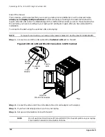
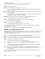
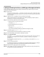
Step 3. Connect one end of a standard LAN cable to the port labeled LAN 1 Customer LAN in Figure F-2
Step 4. Connect the other end of the LAN cable to the local network (customer hub).
Step 5. Power on the SMS and wait about 45 seconds for it to complete its self test.
The power switch on the SMS is at the lower left on the back of the system.
Step 6. On your display device (CE tool, PC/workstation console), ping the default address of the Web
console.
The default IP address for the Web Console is 192.0.0.192.
If the Web console responds, go to step 9. If it does not, go to step 7.
Step 7. On your display device, enter
route add 192.0.0.192 <your IP address>
.
Step 8. Ping the IP address 192.0.0.192 again.
If it responds, continue. If it does not, try using a display device that is connected to the same “c”
class subnet as the Web console and built-in port. Or, enter the command
arp -s 192.0.0.192
<MAC_address of Web console>
. (The MAC address is on a label at the back of the A180.) Then,
repeat step 6.
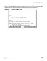
Step 9. After the Web console responds to a ping command, run your Web browser.
You can use Netscape or Internet Explorer. Make sure the version number is 3.02 or above.
PC/Workstation
Console Access
NOTE:
Preferred method
of GSP access
CE Tool (PC)
For initial install of SMS,
serial cable 24542G needed.
Customer Site LAN
(if desired)
Modem
Private LAN Port
Customer LAN Port
RS232 Local
RS232 Remote
Guardian Service
Processor (GSP)
*LAN Hub
0000
LAN Console
Port
10/100 Base-T Port
Support Management
Station
High Availability Observatory
or other info structure to
remotely connect to the
HP Service Location or
customer site LAN.
Содержание 9000 Superdome
Страница 8: ...Contents 8 ...
Страница 9: ...9 Preface ...
Страница 21: ...21 IEC 60417 IEC 335 1 ISO 3864 IEC 617 2 International Symbols ...
Страница 22: ...22 Figure 9 Superdome Declaration of Conformity Page 1 ...
Страница 23: ...23 Figure 10 Superdome Declaration of Conformity Page 2 ...
Страница 24: ...24 ...
Страница 32: ...Chapter 1 Introduction Installation Warranty 8 ...
Страница 130: ...Chapter 4 Verifying and Booting Superdome Enabling iCOD 106 ...
Страница 146: ...Chapter 6 Troubleshooting and Installation Related Tasks Installing a PCI I O Card While the Cell is Off 122 ...
Страница 154: ...Chapter 7 No Boot Disk Superdome Installations Installing the Superdome Operating System From Available Media 130 ...
Страница 172: ...Appendix A hp Server rx2600 Support Management Station Configuring the SMS 148 ...
Страница 184: ...Appendix C Superdome LAN Interconnect Diagram 160 ...
Страница 193: ...Appendix F 169 F A180 Support Management Station ...
Страница 230: ...Appendix G Connecting Multiple SPU Cabinets Connecting Cables 206 ...
Страница 256: ...Appendix H JUST Exploration Tool Error Conditions 232 ...

