


18
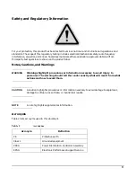
CAUTION
For supply connections, use wires suitable for at least 105 °C.
Utillser des fils convenant á une température de 105 °C pour les connexions d’allmenation.
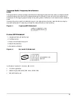
Network Connected Equipment
The installation must provide a ground connection for the network equipment.
CAUTION
Sweden: Apparaten skall anslutas till jordat uttang när deb abskuts till ett nätverk.
CAUTION
Norway: Apparaten skall anslutas till jordat uttang nar deb abskuts till ett natverk.
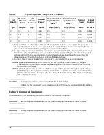
4
4
2
5280
25
20
4300
14,660
2
16
2
4740
20
20
3820
13,030
2
8
2
4380
20
20
3540
12,070
2
4
2
4200
20
20
3400
11,600
a. These numbers are valid only for the specific configurations shown. Any upgrades may require a
change to the breaker size. A 5-wire source utilizes a 4 pole breaker and a 4-wire source utilizes a 3
pole breaker. The PE (Protective Earth) ground wire is not switched.
b. An input power source supplied from a 3-pole plus protective earth (PE), 4-wire system will always
be wired as 240 volts phase-to-phase, no neutral or common, plus a PE ground. Three phase input
voltage (240VAC) to the equipment is connected phase-to-phase. Examples of 4 wire: 200-volt
phase-to-phase, 208-volt phase-to-phase, 240-volt phase-to-phase
c. An input power source supplied from a 4-pole +PE, 5 wire system may be wired as either:
208VAC phase-to-phase voltage with a common, plus a PE ground. Three phase input voltage
(208VAC) to the equipment is connected phase-to-phase. The common is not connected to the
PDCA neutral terminal.
415VAC phase-to-phase voltage with a neutral return, plus a PE ground. Three phase input voltage
(230-240VAC) to the equipment is connected phase-to-neutral. The neutral is connected to the
PDCA neutral terminal. Examples of 5 wire: 208-volt phase-to-phase, 380-volt phase-to-phase,
415-volt phase-to-phase
Table 4
Typical Superdome Configurations (Continued)
Cell
Boards
Memory
Per Cell
Board
I/O
Chassis
Modules
Breaker
Power
a
Recommended
3-pole Breaker
Size
a,b
Recommended
4-pole Breaker
Size
a,c
Typical
Power
Typical
Cooling
Qty.
GBytes
Qty.
Watts
Amps (min.)
Amps (min.)
Watts
BTU/HR
Содержание 9000 Superdome
Страница 8: ...Contents 8 ...
Страница 9: ...9 Preface ...
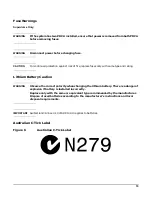
Страница 21: ...21 IEC 60417 IEC 335 1 ISO 3864 IEC 617 2 International Symbols ...
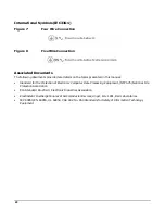
Страница 22: ...22 Figure 9 Superdome Declaration of Conformity Page 1 ...
Страница 23: ...23 Figure 10 Superdome Declaration of Conformity Page 2 ...
Страница 24: ...24 ...
Страница 32: ...Chapter 1 Introduction Installation Warranty 8 ...
Страница 130: ...Chapter 4 Verifying and Booting Superdome Enabling iCOD 106 ...
Страница 146: ...Chapter 6 Troubleshooting and Installation Related Tasks Installing a PCI I O Card While the Cell is Off 122 ...
Страница 154: ...Chapter 7 No Boot Disk Superdome Installations Installing the Superdome Operating System From Available Media 130 ...
Страница 172: ...Appendix A hp Server rx2600 Support Management Station Configuring the SMS 148 ...
Страница 184: ...Appendix C Superdome LAN Interconnect Diagram 160 ...
Страница 193: ...Appendix F 169 F A180 Support Management Station ...
Страница 230: ...Appendix G Connecting Multiple SPU Cabinets Connecting Cables 206 ...
Страница 256: ...Appendix H JUST Exploration Tool Error Conditions 232 ...