


Chapter 3
Preparing Superdome for Booting
Connecting the Cables
76
Connecting the Cables
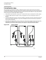
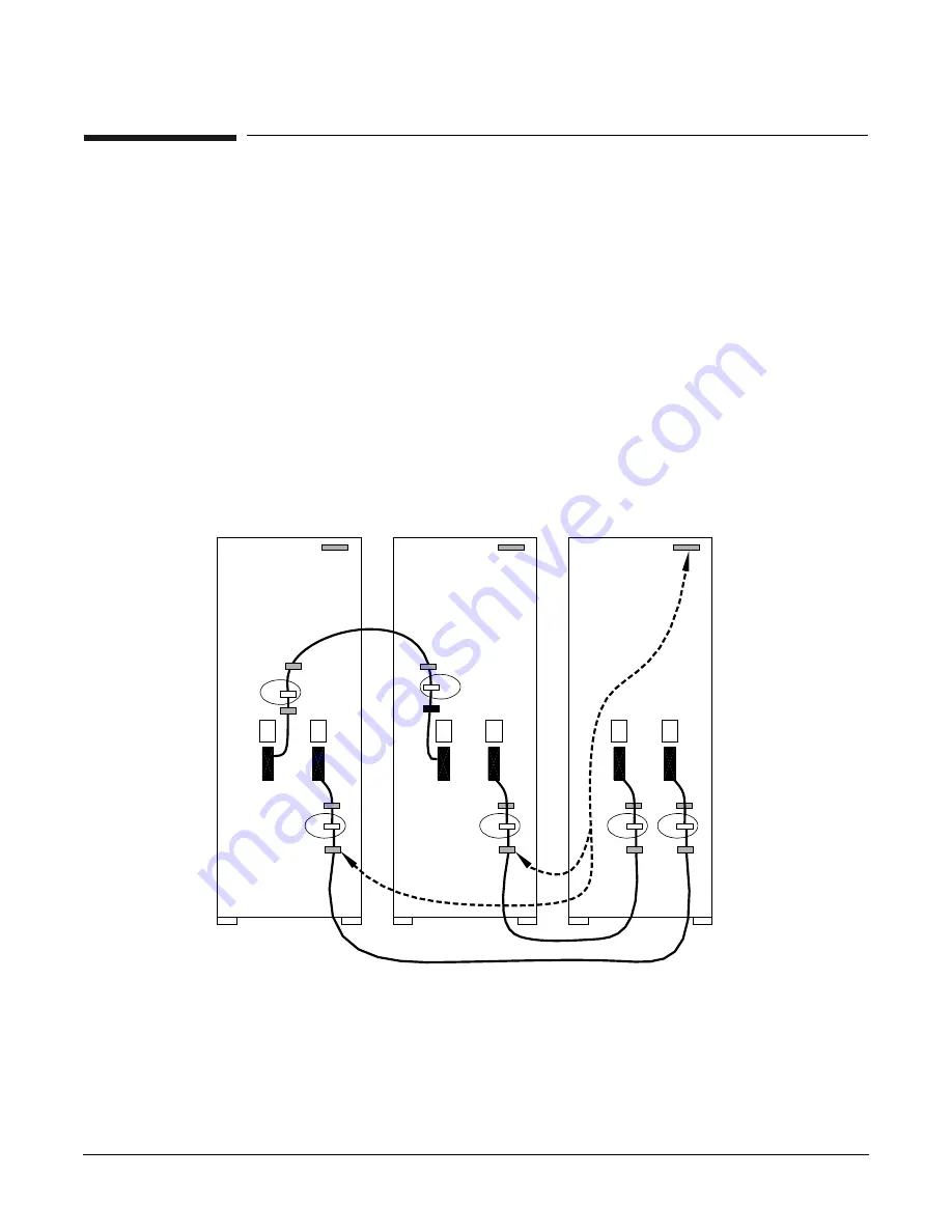
When shipped, the Superdome I/O cables are attached and tied inside the cabinet. When the system is
installed, these cables must be untied, routed, and connected to the cabinets where the other end of the cables
terminate. Use the following guidelines and Figure 3-33 to route and connect cables. For more information on
cable routing, refer to “Routing I/O Cables” on page 77.
•
Each cabinet is identified with a unique color. The cabinet color label is located at the top of the cabinet.
•
The colored label closest to the cable connector corresponds to the color of the cabinet to which it is
attached.
•
The colored label farther away from the cable connector corresponds to the color of the cabinet where the
other end of the cable is attached. In Figure 3-33, the dotted lines show where the label is located and
where the cable terminates.
•
Each cable is also labeled with a unique number. This number label is applied on both ends of the cable
and near the port where the cable is to be connected. In Figure 3-33, the cable number labels are
indicated by circled numbers and the cabinet port numbers are indicated with boxed numbers.
Figure 3-33
Cable Labeling
60IN080A
9/27/00
1
2
1
1
3
1
2
3
2
3
2
3
Содержание 9000 Superdome
Страница 8: ...Contents 8 ...
Страница 9: ...9 Preface ...
Страница 21: ...21 IEC 60417 IEC 335 1 ISO 3864 IEC 617 2 International Symbols ...
Страница 22: ...22 Figure 9 Superdome Declaration of Conformity Page 1 ...
Страница 23: ...23 Figure 10 Superdome Declaration of Conformity Page 2 ...
Страница 24: ...24 ...
Страница 32: ...Chapter 1 Introduction Installation Warranty 8 ...
Страница 130: ...Chapter 4 Verifying and Booting Superdome Enabling iCOD 106 ...
Страница 146: ...Chapter 6 Troubleshooting and Installation Related Tasks Installing a PCI I O Card While the Cell is Off 122 ...
Страница 154: ...Chapter 7 No Boot Disk Superdome Installations Installing the Superdome Operating System From Available Media 130 ...
Страница 172: ...Appendix A hp Server rx2600 Support Management Station Configuring the SMS 148 ...
Страница 184: ...Appendix C Superdome LAN Interconnect Diagram 160 ...
Страница 193: ...Appendix F 169 F A180 Support Management Station ...
Страница 230: ...Appendix G Connecting Multiple SPU Cabinets Connecting Cables 206 ...
Страница 256: ...Appendix H JUST Exploration Tool Error Conditions 232 ...