


Appendix A
hp Server rx2600 Support Management Station
Configuring the SMS
143
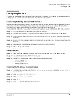
Configuring the SMS
The SMS normally comes from the factory fully configured. If, however, the hp Server rx2600 should require
setting up at the customer location, this section describes the configuration.
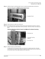
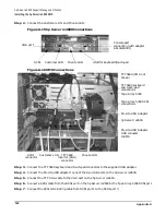
Connecting to the hp Server rx2600 Console
Before the optional SMS VGA monitor (TFT5600) can be used, the boot paths and operating system must be
configured. To control this configuration process, a special adapter (part number A6144-63001) must be
connected to the 25-pin DIN connector on the back of the hp Server rx2600 marked
CONSOLE/REMOTE/UPS. The adapter has three 9-pin “pigtails,” labelled CONSOLE. REMOTE, and UPS.
Step 1. Plug in the hp Server rx2600 but do not power up the unit.
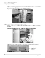
Step 2. Connect a serial device or PC, such as the CE laptop, into the 9-pin DIN marked CONSOLE.
Step 3. Bring up a communication window on the serial device such as Hyper-Term or Reflection for UNIX
and Digital.
Step 4. When the MP Menu appears, select the Command Menu and use the
lc
command to configure the
MP LANs.
Step 5. Once the LANs are configured, enter
ma
to return to the Main MP Menu.
Step 6. Enter
co
to open the console.
EFI Boot Paths
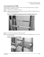
Step 1. Power on the SMS by applying power first to the TFT5600 and then the hp Server rx2600.
Step 2. Escape the boot sequence at EFI. Press any key.
Step 3. Validate on EFI boot menu that the path defaults are set a s follows:
•
primary: 0/1/1/0.0.0
•
secondary: 0/1/1/0.1.0
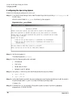
Enabling the VGA Local Console Output
Step 1. From the console window, go to the B
oot Option Maintenance Menu
and select
Active Console
Output Devices
.
Step 2. Select
Acpi(HWP0002,700)/Pci(2|0)
.
Step 3. Select
Save Settings to NVRAM
.
Step 4. Select
Exit
.
Step 5. Select
Exit
again to go back to the main menu.
Содержание 9000 Superdome
Страница 8: ...Contents 8 ...
Страница 9: ...9 Preface ...
Страница 21: ...21 IEC 60417 IEC 335 1 ISO 3864 IEC 617 2 International Symbols ...
Страница 22: ...22 Figure 9 Superdome Declaration of Conformity Page 1 ...
Страница 23: ...23 Figure 10 Superdome Declaration of Conformity Page 2 ...
Страница 24: ...24 ...
Страница 32: ...Chapter 1 Introduction Installation Warranty 8 ...
Страница 130: ...Chapter 4 Verifying and Booting Superdome Enabling iCOD 106 ...
Страница 146: ...Chapter 6 Troubleshooting and Installation Related Tasks Installing a PCI I O Card While the Cell is Off 122 ...
Страница 154: ...Chapter 7 No Boot Disk Superdome Installations Installing the Superdome Operating System From Available Media 130 ...
Страница 172: ...Appendix A hp Server rx2600 Support Management Station Configuring the SMS 148 ...
Страница 184: ...Appendix C Superdome LAN Interconnect Diagram 160 ...
Страница 193: ...Appendix F 169 F A180 Support Management Station ...
Страница 230: ...Appendix G Connecting Multiple SPU Cabinets Connecting Cables 206 ...
Страница 256: ...Appendix H JUST Exploration Tool Error Conditions 232 ...