


16
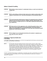
Install a PE (protective earthing) conductor that is identical in size, insulation
material, and thickness to the branch-circuit supply conductors. The PE conductor
insulation must be green with yellow stripes. The earthing conductor is to be
connected from the unit to the building installation earth or, if supplied by a
separately derived system, at the supply transformer or motor-generator set
grounding point.
WARNING
NORDIC Class 1 Equipment
Denmark: Før tilslutning af de øvrige ledere, se medfølgende
installationsvejledning.
WARNING
NORDIC Class 1 Equipment
Sweden: Apparaten skall anslutas till jordat uttag, när den ansluts till ett nätverk.
Disconnect DevicesDisconnect devices or circuit breakers must be used to protect the system against
abnormal hazards. Table 3 details the circuit breaker specifications.
WARNING
Provide a disconnect device to protect against abnormal hazards.
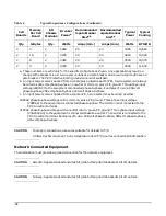
Systems configured with a full complement of cells, memory, and I/O and connected
to a 5-wire source must have a maximum 60A 3-phase with neutral (4-pole) circuit
breaker installed as part of the building installation.
Systems configured with a full complement of cells, memory, and I/O and connected
to a 4-wire source must have a maximum 80A 3-phase (3-pole) circuit breaker
installed as part of the building installation.
Table 3
Wall Disconnect Device Circuit Breaker Specification
Agency approvals:
UL, CSA, VDE
Interrupt capacity
5,000A minimum
Breaker type
Magnetic trip
Voltage rating
Delta 250V minimum, WYE 420V minimum
Input Source
Delta 3 pole + PE, WYE 4 pole + PE
Circuit Interruption
Simultaneous trip of all poles
Ground
The PE (Protective Earth Ground) wire is not
switched
Содержание 9000 Superdome
Страница 8: ...Contents 8 ...
Страница 9: ...9 Preface ...
Страница 21: ...21 IEC 60417 IEC 335 1 ISO 3864 IEC 617 2 International Symbols ...
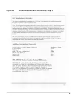
Страница 22: ...22 Figure 9 Superdome Declaration of Conformity Page 1 ...
Страница 23: ...23 Figure 10 Superdome Declaration of Conformity Page 2 ...
Страница 24: ...24 ...
Страница 32: ...Chapter 1 Introduction Installation Warranty 8 ...
Страница 130: ...Chapter 4 Verifying and Booting Superdome Enabling iCOD 106 ...
Страница 146: ...Chapter 6 Troubleshooting and Installation Related Tasks Installing a PCI I O Card While the Cell is Off 122 ...
Страница 154: ...Chapter 7 No Boot Disk Superdome Installations Installing the Superdome Operating System From Available Media 130 ...
Страница 172: ...Appendix A hp Server rx2600 Support Management Station Configuring the SMS 148 ...
Страница 184: ...Appendix C Superdome LAN Interconnect Diagram 160 ...
Страница 193: ...Appendix F 169 F A180 Support Management Station ...
Страница 230: ...Appendix G Connecting Multiple SPU Cabinets Connecting Cables 206 ...
Страница 256: ...Appendix H JUST Exploration Tool Error Conditions 232 ...


