Chapter 4
Verifying and Booting Superdome
Booting Superdome Partitions
89
Step 3. At the GSP Command Menu, enter a number for one of the partitions.
This is the first partition you will boot. Later you will boot the remaining partitions.
Step 4. In a few moments, press Enter once or twice and you should see the BCH prompt (Main Menu:
Enter command or menu>).
Step 5. Enter
ma
to verify that you are in the BCH Main Menu.
Step 6. Enter
pa
to display the path for the partition you selected in step 3.
The Path command lists the paths for the primary, High Availability (HA) alternative, and the
alternate boot paths as they are configured from the factory. The customer may want to change
what device they boot from.
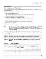
Step 7. Fill in the Primary Boot Path column of Table 4-1 with the primary boot path for the partition
you selected in step 3.
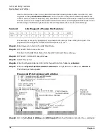
Step 8. Check with the customer that the boot paths are correct for the devices they want to boot from. If
they are not, change the boot path.
NOTE
Remember that the third value in the path represents the Local Bus Adapter
Number, or Rope number. You have to translate the physical slot number to the Rope
number using Table 4-2.
Step 9. Take the first number of the primary boot path in Table 4-1 on page 87, and copy that number into
the Logical Cell # column.
The first number of the primary boot path is the cell number. For example, if the primary boot path
is 0/1/2/3/4/5.6, the logical cell number is 0. From this number you can derive the values for
Physical Cabinet # of Cell and Physical Cell Slot # within Cabinet, columns four and five in
Table 4-1.
Step 10. Fill in the Physical Cabinet # of Cell and the Physical Cell Slot # within Cabinet columns of
These numbers can be derived from the Logical Cell # (column 3 in Table 4-1). Cell numbers are
numbered sequentially beginning at 0. Logical cell numbers for a Superdome 32 Way system range
from 0-7. Logical cell numbers for a Superdome 64 Way system range from 0-15, 0-7 are reserved
for Cabinet 0 and 8-15 are reserved for Cabinet 1.
The first number in the Primary Boot Path represents the logical cell number. If that number is
between 0 and 7, the physical cabinet # for the cell is Cabinet 0 and the physical cell number is the
same as the logical cell number. For example, if the primary boot path is 2/1/2/3/4/5.6, the physical
cabinet number for the cell is Cabinet 0 and the physical cell number is 2.
If the logical cell number is between 8 and 15, the physical cabinet number for the cell is Cabinet 1
and the physical cell number is the logical cell number minus 8. For example, if the primary boot
path is 8/1/8/3/4/5.6, the physical cabinet number for the cell is Cabinet 1 and the physical cell
number is 0. Cell numbers begin at 0 for each cabinet.
Step 11. Fill in the Slot # column of Table 4-1.
You need this information to connect the cable between the boot device and the adapter card for the
boot device.
Содержание 9000 Superdome
Страница 8: ...Contents 8 ...
Страница 9: ...9 Preface ...
Страница 21: ...21 IEC 60417 IEC 335 1 ISO 3864 IEC 617 2 International Symbols ...
Страница 22: ...22 Figure 9 Superdome Declaration of Conformity Page 1 ...
Страница 23: ...23 Figure 10 Superdome Declaration of Conformity Page 2 ...
Страница 24: ...24 ...
Страница 32: ...Chapter 1 Introduction Installation Warranty 8 ...
Страница 130: ...Chapter 4 Verifying and Booting Superdome Enabling iCOD 106 ...
Страница 146: ...Chapter 6 Troubleshooting and Installation Related Tasks Installing a PCI I O Card While the Cell is Off 122 ...
Страница 154: ...Chapter 7 No Boot Disk Superdome Installations Installing the Superdome Operating System From Available Media 130 ...
Страница 172: ...Appendix A hp Server rx2600 Support Management Station Configuring the SMS 148 ...
Страница 184: ...Appendix C Superdome LAN Interconnect Diagram 160 ...
Страница 193: ...Appendix F 169 F A180 Support Management Station ...
Страница 230: ...Appendix G Connecting Multiple SPU Cabinets Connecting Cables 206 ...
Страница 256: ...Appendix H JUST Exploration Tool Error Conditions 232 ...

