


Chapter 3
Preparing Superdome for Booting
Attaching Side Skins and Blower Side Bezels
40
NOTE
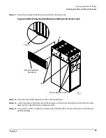
Use four screws to attach the side skins to the top and bottom brackets, except for
the top bracket on the right side (as you face the front of the cabinet). Do not attach
the rear screw on that bracket. Insert all screws but do not tighten until all side
skins are aligned.
Step 5. Repeat Step 1 through Step 4 for the skins on the other side of the cabinet.
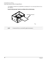
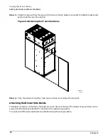
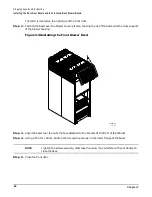
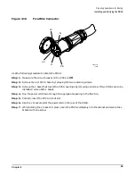
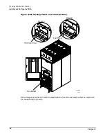
Step 6. To secure the side bezels to the side skins, attach the blower bracket locks (HP P/N A5201-00268) to
the front and back blowers using a T20 Torx driver.
There are two blower bracket locks on the front blowers and two on the rear. Refer to Figure 3-8.
Содержание 9000 Superdome
Страница 8: ...Contents 8 ...
Страница 9: ...9 Preface ...
Страница 21: ...21 IEC 60417 IEC 335 1 ISO 3864 IEC 617 2 International Symbols ...
Страница 22: ...22 Figure 9 Superdome Declaration of Conformity Page 1 ...
Страница 23: ...23 Figure 10 Superdome Declaration of Conformity Page 2 ...
Страница 24: ...24 ...
Страница 32: ...Chapter 1 Introduction Installation Warranty 8 ...
Страница 130: ...Chapter 4 Verifying and Booting Superdome Enabling iCOD 106 ...
Страница 146: ...Chapter 6 Troubleshooting and Installation Related Tasks Installing a PCI I O Card While the Cell is Off 122 ...
Страница 154: ...Chapter 7 No Boot Disk Superdome Installations Installing the Superdome Operating System From Available Media 130 ...
Страница 172: ...Appendix A hp Server rx2600 Support Management Station Configuring the SMS 148 ...
Страница 184: ...Appendix C Superdome LAN Interconnect Diagram 160 ...
Страница 193: ...Appendix F 169 F A180 Support Management Station ...
Страница 230: ...Appendix G Connecting Multiple SPU Cabinets Connecting Cables 206 ...
Страница 256: ...Appendix H JUST Exploration Tool Error Conditions 232 ...