Appendix G
Connecting Multiple SPU Cabinets
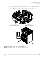
Preparing Cabinet 1 for Connection
185
Preparing Cabinet 1 for Connection
Before you connect the cabinets, prepare Cabinet 1, the right cabinet (as you face the front of the both
cabinets):
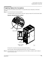
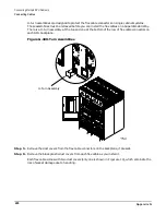
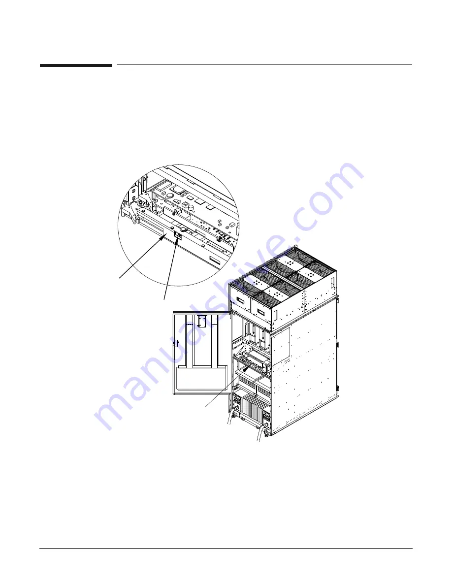
Step 1. Ensure that the UGUY is set as Cabinet 1.
The cabinet number is clearly marked on the UGUY board, just below the Cabinet Number Switch.
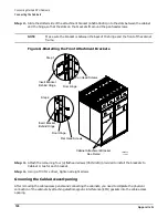
Figure G-4Cabinet Number Location
If the switch is not set to 1, change it by turning the thumbscrew.
Remove the latch catch and associated hardware first; they will be needed later.
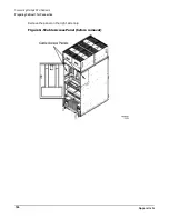
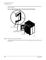
Step 2. Using a T20 driver, remove the cable access panel on the right as you face the rear of Cabinet 1.
Keep the flathead screws.
60IN019A
10/6/00
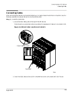
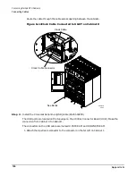
Cabinet 1 (Right)
Rear View
Cabinet Number Switch
UGUY
UGUY
See Detail
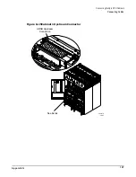
L3-L1
L2-L3
L1-L2
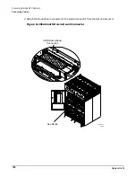
L1-L2
L3-L1
L2-L3
Содержание 9000 Superdome
Страница 8: ...Contents 8 ...
Страница 9: ...9 Preface ...
Страница 21: ...21 IEC 60417 IEC 335 1 ISO 3864 IEC 617 2 International Symbols ...
Страница 22: ...22 Figure 9 Superdome Declaration of Conformity Page 1 ...
Страница 23: ...23 Figure 10 Superdome Declaration of Conformity Page 2 ...
Страница 24: ...24 ...
Страница 32: ...Chapter 1 Introduction Installation Warranty 8 ...
Страница 130: ...Chapter 4 Verifying and Booting Superdome Enabling iCOD 106 ...
Страница 146: ...Chapter 6 Troubleshooting and Installation Related Tasks Installing a PCI I O Card While the Cell is Off 122 ...
Страница 154: ...Chapter 7 No Boot Disk Superdome Installations Installing the Superdome Operating System From Available Media 130 ...
Страница 172: ...Appendix A hp Server rx2600 Support Management Station Configuring the SMS 148 ...
Страница 184: ...Appendix C Superdome LAN Interconnect Diagram 160 ...
Страница 193: ...Appendix F 169 F A180 Support Management Station ...
Страница 230: ...Appendix G Connecting Multiple SPU Cabinets Connecting Cables 206 ...
Страница 256: ...Appendix H JUST Exploration Tool Error Conditions 232 ...


