Appendix H
JUST Exploration Tool
Data Files
230
Node Configuration Files
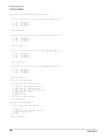
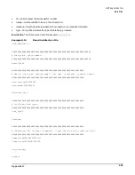
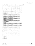
Each node detected by JET gets a node configuration file. These files are named
node_<node number>.cfg
and are placed in the default scan directory
/opt/scansw/data/cplx_<hostname>
. Where hostname is the
name of the complex under test. Theses files define the boards and paths present in each node. This file is
created by the Configuration Management Deamon (
cmd
).
An entry like the following must be supplied for each board in the node:
Board <scan handle> <board name> <board part number>_<scan revision>
An entry like the following must be supplied for each path in the node:
Path <path number>
Each device on the path must have an entry like the following:
Device <scan handle> <mechanical name> <device reference designator> <jtag identifier>
<device name>
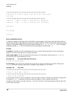
The
mechanical name
field in the device descriptor line identifies a unique name for the device. This unique
name is used by DSU to delineate between common devices on a scan path and is identified in the
partname.lst
file.
Flex Link Mating File
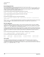
The flex link mating file contains information on the non-static connections within the system, needed to
determine how the current system is connected. There is only one flex link file for a complex, and it must be
named
flex.mte.
JET places this file in the default scan directory
/opt/scansw/data/cplx_<hostname>
.
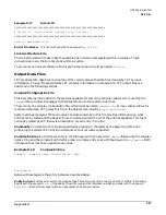
The flex.mate file specifies all flex and cable connections for a complex. This file only contains information on
all possible links that could exist in the complex base on the hardware present. Links that don't exist because
hardware is not present are not listed. This file is generated by the Configuration Management Deamon
(
cmd
).
An entry like the following must be present for each existing or possible link in the complex:
Link <cable scan handle> <cable part number> <cable name>
An entry like the following must exist for each connector on the link:
Mate <cable type> <board scan handle> <connector ref des> <cable ref des>
Mate <cable type> <board scan handle> <connector ref des> <cable ref des>
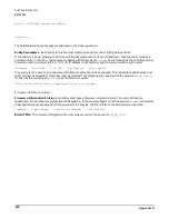
JET Log File
JET writes its execution information (errors and general informational) into a log file. The level of
information is controlled by the debug level parameter in the
jet.cfg
file. This file is the first level for
understanding problems encountered during JET execution. The name and location of this file are controlled
by the
Log_File
parameter in the
jet.cfg
file.
Содержание 9000 Superdome
Страница 8: ...Contents 8 ...
Страница 9: ...9 Preface ...
Страница 21: ...21 IEC 60417 IEC 335 1 ISO 3864 IEC 617 2 International Symbols ...
Страница 22: ...22 Figure 9 Superdome Declaration of Conformity Page 1 ...
Страница 23: ...23 Figure 10 Superdome Declaration of Conformity Page 2 ...
Страница 24: ...24 ...
Страница 32: ...Chapter 1 Introduction Installation Warranty 8 ...
Страница 130: ...Chapter 4 Verifying and Booting Superdome Enabling iCOD 106 ...
Страница 146: ...Chapter 6 Troubleshooting and Installation Related Tasks Installing a PCI I O Card While the Cell is Off 122 ...
Страница 154: ...Chapter 7 No Boot Disk Superdome Installations Installing the Superdome Operating System From Available Media 130 ...
Страница 172: ...Appendix A hp Server rx2600 Support Management Station Configuring the SMS 148 ...
Страница 184: ...Appendix C Superdome LAN Interconnect Diagram 160 ...
Страница 193: ...Appendix F 169 F A180 Support Management Station ...
Страница 230: ...Appendix G Connecting Multiple SPU Cabinets Connecting Cables 206 ...
Страница 256: ...Appendix H JUST Exploration Tool Error Conditions 232 ...

