


Chapter 4
Verifying and Booting Superdome
Booting Superdome Partitions
91
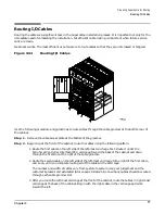
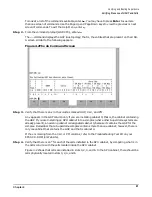
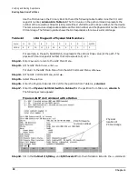
In the example screen above, cabinet refers to the SPU cabinet number (which can have values of 0
- 7 for SPU cabinets, and 8 and above for Expansion Cabinets), MIOB refers to the Master I/O
Backplane (sometimes referred to an I/O bay), which can have values of 0 for the front of the SPU
cabinet and 1 for the back, and slot refers to the PCI card cage chassis number (which can have
values of 1 and 3 (right to left, respectively) for the front and back of the SPU cabinet).
If the PCI card cages are located in an Expansion Cabinet (which would be true for cabinet
numbers of 8 and higher), the MIOB can have values of 0, 1, or 2 (from the bottom of the cabinet to
the top) and slots (PCI card cage chassis number) can have values of 0 and 3, from left to right.
NOTE
Card cage slot numbers for card cages in an Expansion Cabinet are sequenced from
11-0 (bottom to top) for card cages on the left side of the cabinet and 0-11 (bottom to
top) for card cages on the right side of the cabinet.
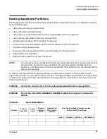
Step 19. Repeat this procedure for each partition you listed in Table 4-1, then continue.
Setting Up the Boot Device
In some cases, a boot device is shipped with the Superdome system. In other cases, the customer already has
a boot device. If the customer already has a boot device, cable it to the appropriate I/O adapter card. More
often than not, the boot device adapter card is located in the SPU cabinet.
The procedure that follows describes the steps to set up the boot device:
Step 1. Install the boot device (if required), or have the customer identify the location of the existing boot
device.
Step 2. Shut down the cell.
Before connecting the cable between the boot device and the boot device adapter card, you need to
power off the cell that communicates with the boot device adapter card.
1. At the GSP Main Menu, enter
cm
.
If you are at the BCH prompt, enter
Ctrl B
to return to the GSP.
2. Enter
pe
(for Power Entity).
3. Enter
c
(for cell).
4. Enter the following information for the partition you want to boot:
•
Cabinet number (the Physical Cabinet # for Cell from Table 4-1, column 4. Enter 0 (zero)
if the cabinet contains the GSP.)
•
Slot number (the Physical Cell Slot # within Cabinet from Table 4-1, column 5).
5. Select off or press Enter.
When you power down the cell, you also power down the card cage that is cabled to that cell.
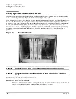
6. Verify that the cell is off, by checking the LED on the cell board.
Step 3. Install the boot device adapter card in the slot specified in column 6 in Table 4-1.
Step 4. Connect the cable between the boot device and the boot device adapter card.
Содержание 9000 Superdome
Страница 8: ...Contents 8 ...
Страница 9: ...9 Preface ...
Страница 21: ...21 IEC 60417 IEC 335 1 ISO 3864 IEC 617 2 International Symbols ...
Страница 22: ...22 Figure 9 Superdome Declaration of Conformity Page 1 ...
Страница 23: ...23 Figure 10 Superdome Declaration of Conformity Page 2 ...
Страница 24: ...24 ...
Страница 32: ...Chapter 1 Introduction Installation Warranty 8 ...
Страница 130: ...Chapter 4 Verifying and Booting Superdome Enabling iCOD 106 ...
Страница 146: ...Chapter 6 Troubleshooting and Installation Related Tasks Installing a PCI I O Card While the Cell is Off 122 ...
Страница 154: ...Chapter 7 No Boot Disk Superdome Installations Installing the Superdome Operating System From Available Media 130 ...
Страница 172: ...Appendix A hp Server rx2600 Support Management Station Configuring the SMS 148 ...
Страница 184: ...Appendix C Superdome LAN Interconnect Diagram 160 ...
Страница 193: ...Appendix F 169 F A180 Support Management Station ...
Страница 230: ...Appendix G Connecting Multiple SPU Cabinets Connecting Cables 206 ...
Страница 256: ...Appendix H JUST Exploration Tool Error Conditions 232 ...