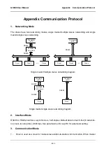
GK600 User Manual Appendix Communication Protocol
- 251 -
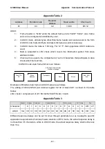
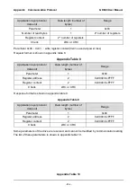
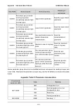
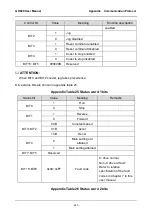
Appendix Table 2
Address
Function code
Register
address
Read words
Check sum
01
03
02
13 88
B5 12
ASCII:
1
)
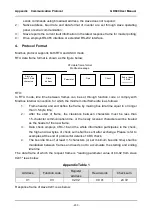
Frame header is "0x3A" while the default frame end is "0x0D" "0x0A"; also, frame
end can be configured and defined by user;
2
)
In ASCII mode, all data bytes other than frame header and end are sent in the form
of ASCII code; high-4-bit byte and low-4-bit byte are sent successively;
3
)
In ASCII mode, the data is 7-bit long. For 'A'~'F', their uppercase ASCII codes are
used;
4
)
Data is subjected to LRC check which covers the information portion from slave
address to data;
5
)
Check sum is equal to the complement of sum of characters that participate in data
check (abort the feed bit).
In ASCII mode, data frame format is as follows:
Examples of Modbus data frame in ASCII mode are as follows.
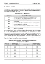
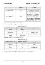
The writing of 4000 (0xFA0) into internal register 02 02 of slave 0x01 is shown in the table
below.
LRC check = complement of (01+06+02+02+0x0F+0xA0) = 0x46
Appendix Table 3
Header Address Parameter
Register address
Write-in content
LRC check
End
Character :
0 1 0 6 0 2 0 2 0 F A 0
4
6 CR LF
ASCII
3A 30 31 30 36 30 32 30 32 30 46 41 30 34 36 0D 0A
Different response delays can be set for drive through parameters so as to adapt to specific
application requirements of various master stations; in RTU mode, the actual response delay is
not less than 3.5 characters, while in ASCII mode, the actual response delay shall not be less
than 1ms.
数据
校验
功能码
从机地址
起始
:
“
0x3A
”
结束
:
“
0xD,0xA
”
Modbus
报文
ASCII
数据帧格式
Check
ASCII data frame format
Modbus message
Start: "0 x
3A
Slave
address
Parameter
Data
End: 0xD,
0xA

