GK600 User Manual
Chapter 6 Specification of Parameters
-
151 -
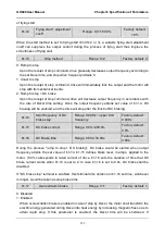
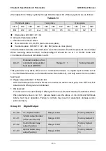
input" (C0-06 is set to 24).
25: Motor 1/2 switchover
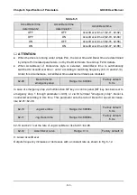
The loaded motor can be selected via this terminal as shown in Table 6-9:
Table 6-9
A0-08
Motor 1/2 switchover
terminal
Loaded motor
0
OFF
Motor 1
0
ON
Motor 2
1
OFF
Motor 2
1
ON
Motor 1
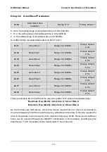
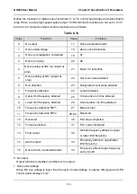
Set parameters of motor 1 in parameter groups d0~d2, and set parameters of motor 2 in
groups d3~d5.
26: Reserved
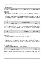
27: Run command switched to control panel control
This terminal should be enabled by trigger edge. When this terminal status is switched from
OFF to ON, run command will be switched to control panel control.
28: Run command switched to terminal control
This terminal should be enabled by trigger edge. When this terminal status is switched from
OFF to ON, run command will be switched to terminal control.
29: Run command switched to communication control
This terminal should be enabled by trigger edge. When this terminal is switched from OFF
to ON, run command will be switched to communication control.
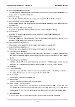
30: Frequency set mode shift
When b0-00 is set to 2, 3 and 4, switch during various frequency set mode can be
performed via "frequency set mode shift" terminal.
When b0-00 is set to 2, this terminal shall shift between master frequency setting and
auxiliary frequency setting.
When b0-00 is set to 3, this terminal shall shift between master frequency setting, and
master & auxiliary computation result.
When b0-00 is set to 4, this terminal shall shift between auxiliary frequency setting, and
master & auxiliary computation result.
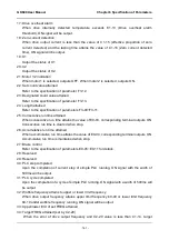
31: Master frequency setting switched to digital setting b0-02
When this terminal is disabled, b0-01 determines master frequency setting. When it is
enabled, master frequency setting is forcibly switched to the value of b0-02.
ATTENTION:
This terminal is disabled when the binding of run command and frequency setting is set by
b1-01.

