GK600 User Manual
Chapter 6 Specification of Parameters
-
127 -
ATTENTION:
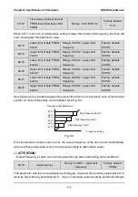
When analog input channel of auxiliary frequency set is the same with that of master
frequency set, analog input channel of auxiliary frequency set would be disabled. See b0-05
and b0-06 for information, about frequency relation that corresponds to maximum value of
analog input of auxiliary frequency
.
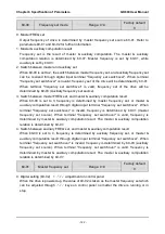
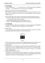
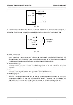
6: X6/DI pulse input
Auxiliary frequency command is determined by pulse frequency via terminal X6/DI only. In
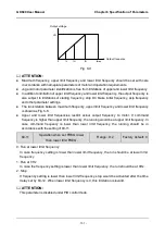
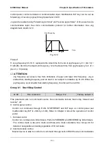
such a case, set X6/DI terminal to "pulse input"(set C0-06 to 24). Refer to C2-24~C2-27 for
corresponding relationship between pulse frequency and command frequency.
ATTENTION:
In case X6/DI pulse input is also set for master frequency command source, the pulse input
for auxiliary frequency command shall be disabled. See b0-05 and b0-06 for information
about frequency relation that corresponds to maximum value of pulse input for auxiliary
frequency command.
7: Process PID output
Auxiliary frequency setting is determined by process PID computation result. See parameter
Group F0 for details.
ATTENTION:
In case PID output is also set for master frequency setting, the process PID output for
auxiliary frequency setting would be disabled. See b0-05 and b0-06 for information about
frequency relation that corresponds to maximum value of process PID output for auxiliary
frequency setting.
8: PLC
Auxiliary frequency setting is determined by simple PLC. See parameter Group F2 for
details.
ATTENTION:
In case simple PLC program output is also set for master frequency setting, the PLC for
auxiliary frequency setting would be disabled.
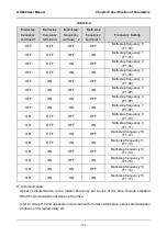
9: Multi-step speed
A total of 16-step speed settings can be realized through status combination of "multi-step
frequency terminal 1~4". Frequency setting can be switched via different combination of
multi-step frequency terminals no matter in running or in stop.
ATTENTION:
In case master frequency setting is also set to multi-step speed, the multi-step speed output
for auxiliary frequency setting would be disabled.

