Chapter 6 Specification of Parameters GK600 User Manual
- 124 -
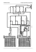
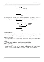
Fig. 6-3
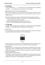
If 10V power supply inside the drive is used with potentiometer, the connection diagram is
shown as Fig. 6-4. Note that the jumper switch should be switched to voltage input side.
Fig. 6-4
5: X6/DI pulse input
If this parameter value is selected, frequency is determined by pulse frequency input via
terminal X6/DI only. In such a case, C0-06 should be set to 24. Corresponding relation
between pulse frequency and frequency set is specified in C2-24~C2-27.
6: Process PID output
Frequency is set by process closed-loop PID computation result. See parameter Group F0
for details.
7: PLC
Frequency is set by simple PLC. See parameter Group F2 for details.
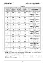
8: Multi-step speed
A total of 16-step speed settings can be realized through status combination of "multi-step
frequency terminal 1~4". See the table below for details. Frequency can be switched via
different combination of multi-step frequency terminals no matter in running or in stop.
AI1
Drive
GND
AI2
`
AI1 Input
AI2 Input
+10V
GND
(
i=1,2
)
AI
(i)
Adjustable
Resistor
Drive

