GK600 User Manual Chapter 6 Specification of Parameters
-
205 -
integral will cease. This mode can quit integral saturation status rapidly.
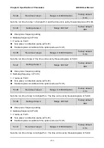
F0-04
PID positive and negative
adjustment
Range: 0~1
Factory default: 0
0: Positive adjustment
1: Negative adjustment
This parameter can be used with digital input terminal "PID adjustment direction" to select
positive or negative adjustment of PID.
Table 6-17
F0-04
PID adjustment direction
terminal
Adjustment
0
OFF
Positive
0
ON
Negative
1
OFF
Negative
1
ON
Positive
Positive adjustment: when feedback signal is smaller than PID setting, output frequency of the
drive will rise to reach PID balance.
when feedback signal is bigger than PID setting, output frequency of the
drive will drop to reach PID balance.
Negative adjustment: when feedback signal is smaller than PID setting, output frequency of the
drive will drop to reach PID balance.
when feedback signal is bigger than PID setting, output frequency of the
drive will rise to reach PID balance.
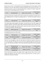
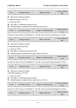
F0-05 Filtering time of PID setting
Range: 0.00s~60.00s
Factory default:
0.00s
F0-06
Filtering time of PID
feedback
Range: 0.00s~60.00s
Factory default:
0.00s
F0-07
Filtering time of PID output
Range: 0.00s~60.00s
Factory default:
0.00s
Set the filtering time of PID setting, feedback and output.
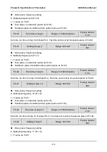
F0-08
Proportional gain Kp1
Range: 0.0~100.0
Factory default:
50.0
F0-09
Integration time Ti1
Range: 0.000s~50.000s
Factory default:
0.500s
F0-10
Derivative time Td1
Range: 0.000s~50.000s
Factory default:
0.0s

