Chapter 6 Specification of Parameters GK600 User Manual
- 126 -
ATTENTION:
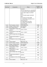
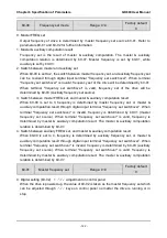
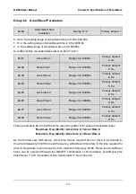
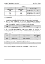
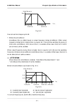
Master frequency can be forcibly switched to b0-02 via terminal "master frequency switched
to digital setting b0-02". When this terminal is disabled, master frequency is determined by
b0-01. When terminal is enabled, master frequency shall be the value of b0-02.
b0-02
Master FREQ digital
setting
Range: lower limit frequency ~
upper limit frequency
Factory default:
50.00Hz
When master frequency setting b0-01 value is set to either 0 or 1, this parameter value will be
the initial value of master frequency setting.
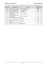
b0-03
Auxiliary FREQ set
Range: 0~10
Factory default:
0
0: No setting
Auxiliary frequency command is disabled, and auxiliary frequency is 0.
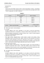
1: Digital setting (b0-04) +
∧
/
∨
adjustment on control panel
When the drive is powered up, the value of b0-04 is auxiliary frequency command, also can
be adjusted through
∧
/
∨
on control panel no matter the drive is running or in stop status.
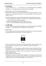
ATTENTION:
When master frequency command involves
∧
/
∨
adjustment on control panel,
∧
/
∨
involving auxiliary frequency command shall be disabled.
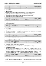
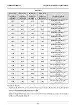
2: digital setting (b0-04) + terminal UP/DOWN adjustment
When the drive is powered up, the value of b0-04 is current auxiliary frequency command.
Whether the drive is running or stopped, current auxiliary frequency setting can be adjusted
through digital input terminals "UP" and "DOWN”. Just set “terminal UP/DOWN frequency
adjustment treatment” and “terminal UP/DOWN frequency change step size” through C0-17
and C0-18.
ATTENTION:
When master frequency setting involves terminal UP/DOWN adjustment, UP/DOWN adjustment
involving auxiliary frequency setting shall be disabled.
3: Analog input AI1
4: Analog input AI2
5: Analog input EAI (on IO option board)
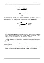
AI1 and EAI can be either (0~10V) voltage input or (0~20mA) current input which can be
switched by the jumper switch on control board or IO option board. AI2 input is -10V~+10V
input only, and the plus/minus of the voltage determines the motor running direction.


