Chapter 2 Interface Signals
311
Ⅲ
Inst
allation
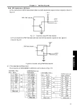
2.3.5 SVC Signal Explanation
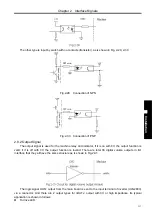
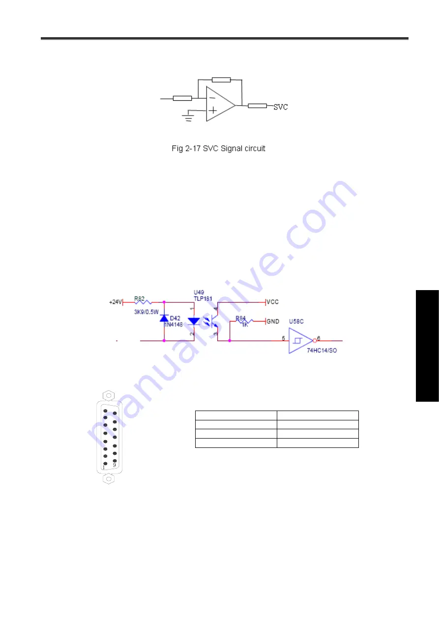
The analog spindle interface SVC can output 0~10V voltage, its interior signal circuit is shown in Fig.
2-17:
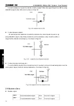
2.3.6 Explanations for ALM5(X5.3)
When the 5
th
axis is valid (namely, it is set to linear axis or rotary axis), this signal is taken as alarm signal of
the 5
th
axis. Level of alarm signal is set by NO.009 ALM5
;
When the 5
th
axis is invalid, the signal is taken as alarm signal of common converter or gear spindle.
F35.0 is 1 in the alarm.
When the 5
th
axis is invalid and ALM5 (X5.3) pin signal is unused, NO.009 is set to 0;
When the 5
th
axis is invalid and ALM5 (X5.3) pin signal is taken as the alarm signal, the Level is set by
NO.009 ALM5;
ALM5
:
0
:
when it is connected with 0V, alarm occurs;
1
:
when it is not connected with 0V, alarm occurs.
2.4 Connection to Spindle Encoder
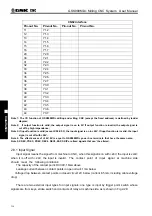
2.4.1 Spindle Encoder Interface Definition
2.4.2 Signal Explanation
PZO-/PZO+, PBO-/PBO+, PAO-/PAO+ are the encoder Z, B, A phase differential input signals
respectively, which are received by 26LS32; MPB-/MPB+, MPA-/MPA+ are normal square wave of phase
shift 90°with the maximum signal frequency less than 1MHz; the encoder pulses for GSK980MDc are set
by data parameter No.3720, whose range is from 0 to 5000.
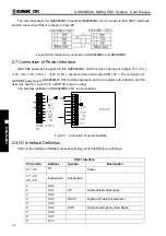
Its interior connection circuit is shown in Fig. 2-19:
(
n=A, B, Z
)
ALMn
Name Explanation
PAO-/PAO+
Encode A phase pulse
PBO-/PBO+
Encode B phase pulse
PZO-/PZO+
Encode Z phase pulse
Fig.2-18 CN21 Encode interface
(DB15 male socket)
8
:
PAO+
7
:
PAO-
6
:
PBO+
5
:
PBO-
4
:
PZO+
3
:
PZO-
2
:
1
:
15
:
GND
14
:
GND
13
:
VCC
12
:
VCC
11
:
GND
10
:
9
:
Содержание 980MDc
Страница 19: ...GSK980MDc Milling CNC User Manual XVIII ...
Страница 20: ...1 I Programming Programming Ⅰ ...
Страница 21: ...GSK980MDc Milling CNC System User Manual 2 I Programming ...
Страница 139: ...GSK980MDc Milling CNC System User Manual 120 I Programming ...
Страница 191: ...GSK980MDc Milling CNC System User Manual 172 I Programming ...
Страница 192: ...173 Ⅱ Operation Ⅱ Operation ...
Страница 193: ...GSK980MDc Milling CNC System User Manual 174 Ⅱ Operation ...
Страница 200: ...Chapter 1 Operation Mode and Display 181 Ⅱ Operation ...
Страница 201: ...GSK980MDc Milling CNC System User Manual 182 Ⅱ Operation ...
Страница 249: ...GSK980MDc Milling CNC System User Manual 230 Ⅱ Operation ...
Страница 253: ...GSK980MDc Milling CNC System User Manual 234 Ⅱ Operation ...
Страница 259: ...GSK980MDc Milling CNC System User Manual 240 Ⅱ Operation ...
Страница 265: ...GSK980MDc Milling CNC System User Manual 246 Ⅱ Operation ...
Страница 293: ...GSK980MDc Milling CNC System User Manual 274 Ⅱ Operation ...
Страница 295: ...GSK980MDc Milling CNC System User Manual 276 Ⅱ Operation ...
Страница 319: ...GSK980MDc Milling CNC System User Manual 300 Ⅱ Operation ...
Страница 320: ...301 Ⅲ Installation Ⅲ Installation ...
Страница 321: ...GSK980MDc Milling CNC System User Manual 302 Ⅲ Installation ...
Страница 345: ...GSK980MDc Milling CNC System User Manual 326 Ⅲ Installation ...
Страница 391: ...GSK980MDc Milling CNC System User Manual 372 Ⅲ Installation ...
Страница 392: ...Appendix 373 Appendix Appendix ...
Страница 393: ...GSK980MDc Milling CNC System User Manual 374 Appendix ...
Страница 394: ...Appendix 375 Appendix Appendix 1 Outline Dimension of GSK980MDc L N ...


