Chapter 6 Screw-Pitch Compensation
371
Ⅲ
Inst
allation
④
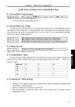
Pitch error compensation of rotary axis
When the additional axis is linear or rotary (B type), the pitch error compensation mode is the
same as the linear axis. The following example explains the pitch error compensation function when
the additional axis is taken as the rotary axis (A type).
No. 1260 (movement amount of rotary per rev) = 360
,
№
3624
(
pitch error compensation interval
)
= 45
№
3620
(
pitch error compensation number corresponded to machine zero
)
= 60
Set the minimum pitch error compensation position number No. 3621 of the rotary axis=50, the maximum
pitch error compensation position number No. 3622=100
After the above parameters are set, the farthest pitch error compensation position number of the rotary axis
in the negative direction is equal to compensation position number of reference point.
The farthest compensation position number in the positive direction is:
Compensation position number of reference point+
(
movement amount per rev/compensation
position interval
)
= 60+360/45 = 68
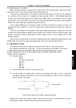
Relations between machine coordinates and compensation position number:
When compensation sum of the position 60
~
68 is not 0, a position error occurs. The sum is an
accumulation of pitch error compensation value per rev. the same compensation values must be set at the
position 60 and 68 as follows:
Compensation
position number
60
61
62
63
64
65 66 67
68
Set compensation
value
+1
-2
+1
+3
-1
-1 -3 +2
+1
Содержание 980MDc
Страница 19: ...GSK980MDc Milling CNC User Manual XVIII ...
Страница 20: ...1 I Programming Programming Ⅰ ...
Страница 21: ...GSK980MDc Milling CNC System User Manual 2 I Programming ...
Страница 139: ...GSK980MDc Milling CNC System User Manual 120 I Programming ...
Страница 191: ...GSK980MDc Milling CNC System User Manual 172 I Programming ...
Страница 192: ...173 Ⅱ Operation Ⅱ Operation ...
Страница 193: ...GSK980MDc Milling CNC System User Manual 174 Ⅱ Operation ...
Страница 200: ...Chapter 1 Operation Mode and Display 181 Ⅱ Operation ...
Страница 201: ...GSK980MDc Milling CNC System User Manual 182 Ⅱ Operation ...
Страница 249: ...GSK980MDc Milling CNC System User Manual 230 Ⅱ Operation ...
Страница 253: ...GSK980MDc Milling CNC System User Manual 234 Ⅱ Operation ...
Страница 259: ...GSK980MDc Milling CNC System User Manual 240 Ⅱ Operation ...
Страница 265: ...GSK980MDc Milling CNC System User Manual 246 Ⅱ Operation ...
Страница 293: ...GSK980MDc Milling CNC System User Manual 274 Ⅱ Operation ...
Страница 295: ...GSK980MDc Milling CNC System User Manual 276 Ⅱ Operation ...
Страница 319: ...GSK980MDc Milling CNC System User Manual 300 Ⅱ Operation ...
Страница 320: ...301 Ⅲ Installation Ⅲ Installation ...
Страница 321: ...GSK980MDc Milling CNC System User Manual 302 Ⅲ Installation ...
Страница 345: ...GSK980MDc Milling CNC System User Manual 326 Ⅲ Installation ...
Страница 391: ...GSK980MDc Milling CNC System User Manual 372 Ⅲ Installation ...
Страница 392: ...Appendix 373 Appendix Appendix ...
Страница 393: ...GSK980MDc Milling CNC System User Manual 374 Appendix ...
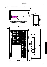
Страница 394: ...Appendix 375 Appendix Appendix 1 Outline Dimension of GSK980MDc L N ...


